More Unbreakable Suburban Episodes
Engine Power Featured Projects
Engine Power Builds
Want more content like this?
Join the PowerNation Email NewsletterParts Used In This Episode
ARP
Bolts & Studs
Forney Industries
Forney Tig Machine
Matco Tools
MATCO Tools are the Official Tool Supplier to PowerNation
The Industrial Depot
Tools, Hardware, Shop Supplies
Episode Transcript
(Pat)>> You're watching Powernation!
(Pat)>> It's not just how much power your engine produces. Where your engine makes power matters too.
(Frankie)>> Today on Engine Power we talk camshaft timing. [ MUSIC ]
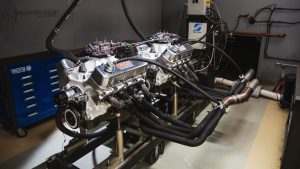
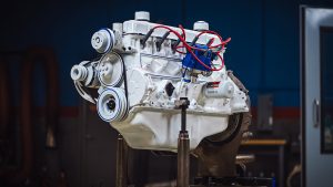
(Frankie)>> Welcome to Engine Power. Today we're gonna be building a very popular combination and you've seen a few of them come out of the shop before. It's gonna be a 383 cubic inch small block Chevy but with a twist. We've ordered some special parts to show you some cool tech on the dyno.
(Pat)>> Now I know what you're thinking. These guys are building another stroked small block Chevy? Are they stuck in the '80's? Well yes and no, but that's a different conversation. Anyway we are doing this for two different reasons. One there is a vehicle in the building that requested this exact combination and two, we are going to show you some stuff on the dyno we haven't shown you in a while. We are gonna show how the camshaft's intake center line affects the power curve of an engine, whether the cam is advanced or retarded a bunch, and you are going to be interested to see the results.
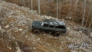
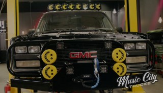
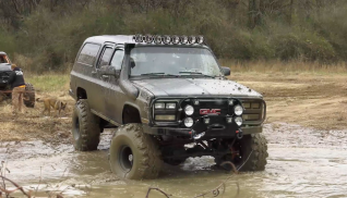
(Frankie)>> A few weeks ago when we heard that Music City Trucks was turning a 1991 Suburban into a 10,000 pound off road rig it peaked our interest.
(Marc)>> We're calling it Unbreakable. This is the ultimate off road rig that you drive to an off road park, wheel all weekend, and drive it home, nothing breaks.
(Frankie)>> So you want it to be reliable.
(Pat)>> That's a tall order, and when they wheeled in the used up stock engine we said thanks but no thanks. Whoa, that's far enough. What is this contraption?
(Brandon)>> This is the 350 out of our Suburban project.
(Frankie)>> What's it doing here?
(Brandon)>> I want you guys to build it.
(Pat)>> This particular engine?
(Brandon)>> Well this is what we got.
(Pat)>> If you name your vehicle Unbreakable the engine better be rock solid. Based on the age and condition of the stock power plant we suspected it was better to start from scratch. When Marc told us a little bit more about their engine needs we knew this was a good plan.
(Marc)>> It's gonna live its life in the low to mid r-p-m range. Sometimes high r-p-m's if we want to do a really high r-p-m run through the mud or something like that, but for the most part low and mid r-p-m range is where it's gonna live.
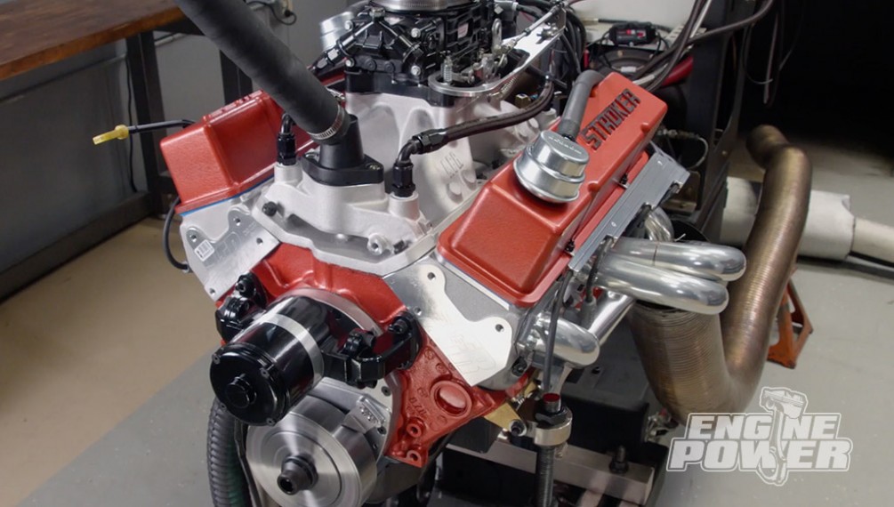
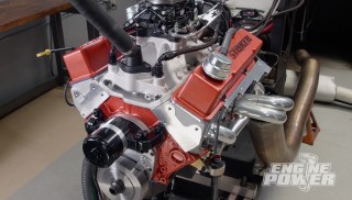
(Pat)>> It's fortunate that we already have a 383 project in process. That way we don't have to tear apart their engine and we have parts already in house. It starts with a fully machined small block Chevy. This is a late model tall lifter roller engine that has already been bored, honed, aligned honed, cam bearings, and freeze plugs installed, and been clearanced for the bigger stroke, and that leads us to the parts that were all available off the shelf from Summit Racing. It starts with an Eagle rotating assembly with a 43-40 forged crank with a 3.750 stroke, a set of Mahle Power Pack pistons with a 5cc valve relief, and a one millimeter, one millimeter, two millimeter ring pack. The connecting rods are a set of Eagle's forged 43-40 I-beams with a six inch center to center length and a bushed pin end. For an induction we used a set of AFR 220 eliminators because we were going to do something different earlier but we can make it work for the application. We also have one of their high rise single plane intakes. For valvetrain we'll be using a Comp Cams solid roller. We were using a solid roller on our other application and we can still use it for this one. We just have to back it down on lift and duration. We also have a set of Harlan Sharp 1.6 ratio rockers and it's all held together by ARP fasteners.
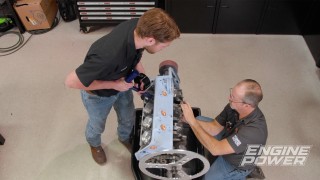
(Frankie)>> Now we're gonna go through our normal process of measuring clearances and filing rings but we're gonna show you a little bit less of it so we have more time for our tech on the dyno, and to do that we're gonna use these. We picked up this Comp Cams billet double roller timing set from Summit Racing. We chose this over other designs for its ease of use and increased accuracy. It has up to six degrees advance and six degrees retard built in. In order to use this setup on the dyno we also picked up a three piece billet aluminum timing cover set. It has a top piece that is removable for easy access to the cam gear adjustment, and the bottom piece is aligned by dowels and comes with a front cover seal already installed. Every good engine build starts with careful measurement of clearances and pre-fitment. Pat usually worries that if we don't show you the work being done you might just assume that we didn't actually do it. Like I said before, we're gonna save some time by showing the work in a high speed time lapse. That way we don't have to worry about Pat's blood pressure and we'll have more time to focus on camshaft timing in a little bit.
(Pat)>> With everything looking good the crankshaft is placed on the slicked up bearings. The ARP main bolts are torqued in sequence to 70 pound feet. [ MUSIC ] Did I tell you that I was reading a book about anti-gravity?
(Frankie)>> No!
(Pat)>> It's impossible to put down! Coming up, on the engine and in the dyno cell we'll show you how camshaft timing affects performance.
(Pat)>> When you are looking for a new set of spark plug wires for your project there are a few different options to consider depending on your application. Basically there are two different types of spark plug wire construction, solid core and spiral core. Solid core wires are for when you want the maximum voltage with the least amount of resistance to your spark plugs. They are readily available in either pre-made sets or in sets that are not terminated at the distributor end so you can make them fit your particular engine. The only drawback to this design of wire is that it sends out lots of r-f-i when it is operating and that will affect other electronic systems in the vehicle. The other type is a spiral core wire. Also available in pre-made or universal sets, this design wraps the core with a blend of stainless, copper, and tin to suppress that r-f-i noise. The only drawback to this style of wire is the more that the core is wrapped for r-f-i suppression the more resistance the wire has to send maximum voltage to the plug, but it is better for vehicles with sensitive electronic equipment. Making up a custom spark plug wire is an easy task with a few tools you can get through Summit Racing. Here we have two different styles of crimping pliers to do the job. Both will produce a good quality crimp to ensure your wires perform to their maximum capabilities. Our 383 stroker build continues with a Comp Cams solid roller camshaft. This is smaller than originally planned but since the guys from Music City Trucks wanted lower r-p-m power it fits the bill nicely. The Comp Cam's billet timing set slips on next held in place by ARP fasteners that will be torqued later. At this point we're mocking up the engine. So we'll install the number one rod and piston assembly without rings for now.
(Frankie)>> True t-d-c is set on our degree wheel. The cam is degreed at 110 degrees of intake center line, which is straight up. A set of lifters are installed in the number one lifter bore location, and a cylinder head equipped with checking springs comes next. Two Harlan Sharp 1.6 ratio rockers are added with a set of Comp Cams push rods. Cold lash is set at 10 thousandths on the intake and 12 thousandths on the exhaust. The point where the exhaust valve is closest to the piston occurs at 10 degrees before top dead center on split overlap. We have 122 thousandths piston to valve clearance. For the intake valve the clearance is 177 thousandths at 10 degrees after top dead center on split overlap.
(Pat)>> We have a ton, miles, of intake clearance. That means we can really advance the cam a ton more than you would ever think you could and still have safe valve clearance. To start off checking clearances we are installing the cam in straight up at 110 degrees of intake centerline, which is the same as the cam's lobe separation. We are gonna try to advance or retard the cam as much as we can as long as we sufficient piston to valve clearance. When you advance the cam the intake valve gets closer to the piston and the exhaust valve gets further away. The opposite happens when you retard the cam. The exhaust valve's clearance gets closer and the intake valve increases. So we will vary it to see how much we have safely in each direction, and that's where we're gonna run it on the dyno.
(Frankie)>> We'll retard the cam as much as we think is safely possible and recheck our clearance.
(Pat)>> Now that's 90. [ MUSIC ] 90 thousandths clearance for piston to valve on the exhaust side is a bit on the tight side. Normally you would want 100 to 120 thousandths just for safety purposes. In our case we are gonna be okay because we will be using a thicker head gasket when we assemble the engine for real. The one we have now is 10 thousandths less than we'll be running. So that will put us in the good. So we will mark that position and then we will advance the cam as much as we think we can and we'll check the intake valve's piston to valve clearance and see what we have. [ MUSIC ] The camshaft in at 100 degrees intake center line, which is 10 degrees advanced. We'll check the exhaust side, which should have increased by a lot. So it's out at 190, 293, switching it to the intake side. At 10 degrees advanced still have basically 100 thousandths clearance. All the piston rings have been file fit with gaps of 22 thousandths on the top ring and 24 thousandths on the second. To ensure proper break-in we're lubing up the rings and cylinders with Total Seal assembly lube. Things go way smoother with a tapered ring compressor from ARP, especially with modern thinner ring packs.
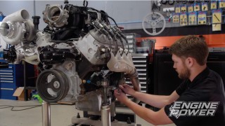
(Frankie)>> Torqueing the rod bolts to 75 pound feet yields 4.5 thousandths of rod bolt stretch, which is in spec for the ARP fastener. As always we check all the fasteners. The three piece timing cover is next. It requires only a thin film of r-t-v to seal it. A little goes a long way. Our Summit Racing s-f-i approved balancer presses on using a harmonic balancer installation tool, not a hammer. The Comp solid roller lifters are lubed and slid into place. They must go in before the cylinder heads are bolted down. [ MUSIC ]
(Pat)>> AFR adjustable guide plates are mocked up along with the rest of the valvetrain so we can align the rockers precisely on the valve tips. Then they are tacked in place using our Forney tig machine. Now the studs get thread sealant and are re-installed. They are torqued to 55 pound feet. With everything setup the rest of the valvetrain is installed in the engine's firing order. Our AFR single plane intake manifold finishes out the bit pieces. It's held in place by ARP fasteners with a black oxide finish.
(Frankie)>> We like our engines to be snazzy. So we'll shoot our engine with a plain red base coat followed by a metallic red engine enamel. The color is red fire. We sprung for a billet O-ring seal oil filter adapter from Summit Racing, which is a big upgrade over the cast aluminum stock piece.
(Pat)>> We bought our oiling system as part of a Summit Pro Pack kit. It includes the oil pump, driveshaft, pickup, one piece oil pan gasket, and a six quart baffled oil pan. Initial timing is set at 30 degrees. The engine is warmed up and hot lash is set at 16 thousandths on the intake and 18 thousandths on the exhaust.
(Frankie)>> Up next, we dial in the power band of our stroker for maximum performance on the trail.
(Pat)>> Alright so we've gone through and ran the engine. We've set the valves and made a few initial pulls to get the carburetor and the timing in the right range. So at 34 degrees of timing we're gonna make a sweep from 3,500 to 6,500 at 300 per second. [ engine revving ]
(Pat)>> 503, 477! How about them apples?
(Frankie)>> That's sweet! For the cam that's in it.
(Pat)>> What a spectacular little street engine. It's got about an inch of manifold vacuum. That's about right. Oil pressure is good. We are two and a half degrees retarded on the camshaft right now. So what I'd like to do is, now that it's at operating temp, let's shut it down before we do anything with the cam. Let's do a cranking compression test because this engine is 10.95 to one static, but with a cam backed all the way up like that the dynamic compression is something like 8.7.
(Frankie)>> This will be a good way to show what actually changes when you actually move the cam from retarded to advance.
(Pat)>> Let's do that right now! Strong cranking compression is a sign of a healthy engine. Ours tests at 170 p-s-i. Later when we advance the camshaft's intake center line both cranking and dynamic compression will increase. You can find several online calculators to help determine your engine's dynamic compression.
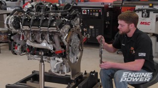
(Frankie)>> To get to the camshaft we just have to drain the block and remove the water pump. The top half of the timing cover comes off next, giving us access to the camshaft timing adjustment. After breaking loose the outside locking bolts we will change the center line by rotating the crankshaft instead of using the adjustment tool. We do this since the cam is under full valvetrain spring pressure. No need to use the degree wheel because we've already set up our timing marks during engine assembly. The camshaft is now at 100 degrees intake center line, which is 10 degrees advanced. The outside locking bolts get re-torqued to 14 pound feet, and after applying silicone the timing cover is re-sealed and reinstalled. Since the engine is still warm we can test our cranking compression again, and it has increased from 170 p-s-i to 205.
(Pat)>> The cam's intake center line is in at 100. Previously 112. I've never done this on the dyno before. So this will be pretty interesting. Timing because you had to move the cam you have to move the timing back to be the same. So we're still at 34 degrees. Are we ready? [ engine revving ]
(Pat)>> It did exactly what it was supposed to. I think it tilted the curve. It pumped up the torque. 491.9 pound feet of torque and 483 horsepower. So it dropped some horsepower but what happened is when you switch the intake center line it changes where the intake valve closes, builds cylinder pressure earlier. So you will sacrifice some top end but pick up some bottom end. We were at 477 to 491.
(Frankie)>> And if we overlay them you can see where it tilts.
(Pat)>> You'll be able to really see where it tilts at. Look at that! You could actually take the curve, if you could unhook them from the screen, you could just put them together. It's the exact same pull it's just now it makes more torque down low, less power up top. We can't get it any further retarded on the other side. So we couldn't go further and show a bigger gain because we'd hit the valves at some point. You can get these advanced so far you can really put the engine into detonation. We're on 93 octane gas. We're still okay. This is a great, great illustration of doing this on the dyno to show what it does for power.
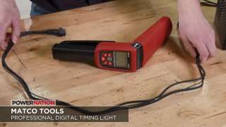
(Frankie)>> High performance engines live or die by ignition timing, and when we're tuning our engines on the dyno we need a timing light that's both versatile and accurate. One of our favorites is this timing light that we picked up from Matco Tools. It has six foot detachable leads that hook right up to 12 volt power like our dyno battery, and a spring loaded clamp style magnetic pickup that is easy to put on and take off. It has a rotating head for easier access into engine bays and one of the nicest parts of this light is the digital display. The back lit screen is super easy to read even in direct sunlight, and it has readouts for battery voltage, timing advance, r-p-m, and even dwell. It can show up to 90 degrees of timing advance and works on 2 and 4 stroke applications with two to 12 cylinders, making it perfect for anything we throw on the dyno. You can find this and any other tools you need at Matco Tools dot com.
(Pat)>> Up next, the guys from Music City Trucks have a decision to make. What do you they will choose?
(Marc)>> It's a no brainer.
(Pat)>> Alright.
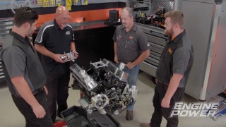
(Pat)>> Alright guys, the engine is done. We wanted you over here not just to see it run but you're gonna have to make a decision about how it runs if that's cool with you. Here's the way it's gonna be in the truck. We used your headers and that does effect power, and we've done some stuff with the cam that will affect power also. You ready?
(Brandon)>> I'm ready.
(Marc)>> Let's do it! [ engine revving ]
(Brandon)>> Not bad!
(Pat)>> Those short headers throw a little fire back out. Okay that's what our power is now. We fuzzed a little bit more timing into and did a couple little things. We're at 490 horsepower at 6,300, but 492 pounds of torque, 492.7, but look how flat your torque curve is right there. Okay I want you to keep that in mind. You want power in a specific range. The first run that we've done with the engine before all this we had the cam's intake center line in at 112.5, which is two degrees retarded. So we've ran it like that to get a power number and then we've taken the cam and advanced it as far as we can, what is allowed by the actual equipment, and now it's in at 100. So we have a 112.5 degree swing on the intake center line from very, very advanced to slightly retarded. What it does to the power is it tips where it makes power. I'm gonna pull a graph up here on our first pull and I'm gonna overlay it.
(Marc)>> While you're doing that I just want to say the engine looks awesome!
(Pat)>> That's Frankie Picasso there.
(Frankie)>> I was trying to get it to match your truck a little bit but it can't be dull. So I had to throw a little something extra at it.
(Pat)>> Okay notice the difference in our graph. If you took this graph and you unhooked these two lines you could actually see their shapes. You could squeeze them together and they make the same curve. So the torque is high and it trails off down low. The power starts off higher and trails off up top. With the cam in the retarded position it starts off a little bit lower on torque but carries further and makes more power up top. Then that's around 5,500. If you have an engine that runs below 5,500 for the majority of its time it will absolutely make more average power. Peak numbers are one thing. Average power is more important 99.9 percent of the time. We can change it. If you want us to change it back, if you want this big number, or if you want to leave it so you have more torque. You almost have 500 pound feet of torque.
(Brandon)>> I like the torque more than the horsepower on that.
(Pat)>> Down low look how much more torque at say 3,500 it has. I mean 455 versus 482.
(Marc)>> This is comparing apples to orange what potentially would the difference be in peak torque as you go lower in the r-p-m range be greater?
(Pat)>> It would exacerbate it more. When you have the cam that far advanced you're trapping air earlier in the cycle. The intake valve is closing sooner, building more cylinder pressure. We did a cranking compression test on it and it was from 170 with the cam in at 112.5 to 205 pounds at 10 degrees advanced.
(Marc)>> So on average below that 5,500 mark we would be averaging at least 15 more pound feet, and possibly even more lower in the r-p-m range that you didn't even sample.
(Pat)>> It has more torque and it has more horsepower.
(Marc)>> It's a no brainer.
(Pat)>> It's a no brainer! Changing where the cam's position is definitely affects where it makes torque and where it makes power.
(Marc)>> I've seen entire cam swaps that didn't make that big of a difference.
(Pat)>> This was a fun one to do. We don't want to hold you up too much. You'll see this in a little bit.
(Marc)>> Thanks guys, awesome!
(Pat)>> And for more information on anything you've see today visit Powernation TV dot com.
Show Full Transcript
(Pat)>> It's not just how much power your engine produces. Where your engine makes power matters too.
(Frankie)>> Today on Engine Power we talk camshaft timing. [ MUSIC ]
(Frankie)>> Welcome to Engine Power. Today we're gonna be building a very popular combination and you've seen a few of them come out of the shop before. It's gonna be a 383 cubic inch small block Chevy but with a twist. We've ordered some special parts to show you some cool tech on the dyno.
(Pat)>> Now I know what you're thinking. These guys are building another stroked small block Chevy? Are they stuck in the '80's? Well yes and no, but that's a different conversation. Anyway we are doing this for two different reasons. One there is a vehicle in the building that requested this exact combination and two, we are going to show you some stuff on the dyno we haven't shown you in a while. We are gonna show how the camshaft's intake center line affects the power curve of an engine, whether the cam is advanced or retarded a bunch, and you are going to be interested to see the results.
(Frankie)>> A few weeks ago when we heard that Music City Trucks was turning a 1991 Suburban into a 10,000 pound off road rig it peaked our interest.
(Marc)>> We're calling it Unbreakable. This is the ultimate off road rig that you drive to an off road park, wheel all weekend, and drive it home, nothing breaks.
(Frankie)>> So you want it to be reliable.
(Pat)>> That's a tall order, and when they wheeled in the used up stock engine we said thanks but no thanks. Whoa, that's far enough. What is this contraption?
(Brandon)>> This is the 350 out of our Suburban project.
(Frankie)>> What's it doing here?
(Brandon)>> I want you guys to build it.
(Pat)>> This particular engine?
(Brandon)>> Well this is what we got.
(Pat)>> If you name your vehicle Unbreakable the engine better be rock solid. Based on the age and condition of the stock power plant we suspected it was better to start from scratch. When Marc told us a little bit more about their engine needs we knew this was a good plan.
(Marc)>> It's gonna live its life in the low to mid r-p-m range. Sometimes high r-p-m's if we want to do a really high r-p-m run through the mud or something like that, but for the most part low and mid r-p-m range is where it's gonna live.
(Pat)>> It's fortunate that we already have a 383 project in process. That way we don't have to tear apart their engine and we have parts already in house. It starts with a fully machined small block Chevy. This is a late model tall lifter roller engine that has already been bored, honed, aligned honed, cam bearings, and freeze plugs installed, and been clearanced for the bigger stroke, and that leads us to the parts that were all available off the shelf from Summit Racing. It starts with an Eagle rotating assembly with a 43-40 forged crank with a 3.750 stroke, a set of Mahle Power Pack pistons with a 5cc valve relief, and a one millimeter, one millimeter, two millimeter ring pack. The connecting rods are a set of Eagle's forged 43-40 I-beams with a six inch center to center length and a bushed pin end. For an induction we used a set of AFR 220 eliminators because we were going to do something different earlier but we can make it work for the application. We also have one of their high rise single plane intakes. For valvetrain we'll be using a Comp Cams solid roller. We were using a solid roller on our other application and we can still use it for this one. We just have to back it down on lift and duration. We also have a set of Harlan Sharp 1.6 ratio rockers and it's all held together by ARP fasteners.
(Frankie)>> Now we're gonna go through our normal process of measuring clearances and filing rings but we're gonna show you a little bit less of it so we have more time for our tech on the dyno, and to do that we're gonna use these. We picked up this Comp Cams billet double roller timing set from Summit Racing. We chose this over other designs for its ease of use and increased accuracy. It has up to six degrees advance and six degrees retard built in. In order to use this setup on the dyno we also picked up a three piece billet aluminum timing cover set. It has a top piece that is removable for easy access to the cam gear adjustment, and the bottom piece is aligned by dowels and comes with a front cover seal already installed. Every good engine build starts with careful measurement of clearances and pre-fitment. Pat usually worries that if we don't show you the work being done you might just assume that we didn't actually do it. Like I said before, we're gonna save some time by showing the work in a high speed time lapse. That way we don't have to worry about Pat's blood pressure and we'll have more time to focus on camshaft timing in a little bit.
(Pat)>> With everything looking good the crankshaft is placed on the slicked up bearings. The ARP main bolts are torqued in sequence to 70 pound feet. [ MUSIC ] Did I tell you that I was reading a book about anti-gravity?
(Frankie)>> No!
(Pat)>> It's impossible to put down! Coming up, on the engine and in the dyno cell we'll show you how camshaft timing affects performance.
(Pat)>> When you are looking for a new set of spark plug wires for your project there are a few different options to consider depending on your application. Basically there are two different types of spark plug wire construction, solid core and spiral core. Solid core wires are for when you want the maximum voltage with the least amount of resistance to your spark plugs. They are readily available in either pre-made sets or in sets that are not terminated at the distributor end so you can make them fit your particular engine. The only drawback to this design of wire is that it sends out lots of r-f-i when it is operating and that will affect other electronic systems in the vehicle. The other type is a spiral core wire. Also available in pre-made or universal sets, this design wraps the core with a blend of stainless, copper, and tin to suppress that r-f-i noise. The only drawback to this style of wire is the more that the core is wrapped for r-f-i suppression the more resistance the wire has to send maximum voltage to the plug, but it is better for vehicles with sensitive electronic equipment. Making up a custom spark plug wire is an easy task with a few tools you can get through Summit Racing. Here we have two different styles of crimping pliers to do the job. Both will produce a good quality crimp to ensure your wires perform to their maximum capabilities. Our 383 stroker build continues with a Comp Cams solid roller camshaft. This is smaller than originally planned but since the guys from Music City Trucks wanted lower r-p-m power it fits the bill nicely. The Comp Cam's billet timing set slips on next held in place by ARP fasteners that will be torqued later. At this point we're mocking up the engine. So we'll install the number one rod and piston assembly without rings for now.
(Frankie)>> True t-d-c is set on our degree wheel. The cam is degreed at 110 degrees of intake center line, which is straight up. A set of lifters are installed in the number one lifter bore location, and a cylinder head equipped with checking springs comes next. Two Harlan Sharp 1.6 ratio rockers are added with a set of Comp Cams push rods. Cold lash is set at 10 thousandths on the intake and 12 thousandths on the exhaust. The point where the exhaust valve is closest to the piston occurs at 10 degrees before top dead center on split overlap. We have 122 thousandths piston to valve clearance. For the intake valve the clearance is 177 thousandths at 10 degrees after top dead center on split overlap.
(Pat)>> We have a ton, miles, of intake clearance. That means we can really advance the cam a ton more than you would ever think you could and still have safe valve clearance. To start off checking clearances we are installing the cam in straight up at 110 degrees of intake centerline, which is the same as the cam's lobe separation. We are gonna try to advance or retard the cam as much as we can as long as we sufficient piston to valve clearance. When you advance the cam the intake valve gets closer to the piston and the exhaust valve gets further away. The opposite happens when you retard the cam. The exhaust valve's clearance gets closer and the intake valve increases. So we will vary it to see how much we have safely in each direction, and that's where we're gonna run it on the dyno.
(Frankie)>> We'll retard the cam as much as we think is safely possible and recheck our clearance.
(Pat)>> Now that's 90. [ MUSIC ] 90 thousandths clearance for piston to valve on the exhaust side is a bit on the tight side. Normally you would want 100 to 120 thousandths just for safety purposes. In our case we are gonna be okay because we will be using a thicker head gasket when we assemble the engine for real. The one we have now is 10 thousandths less than we'll be running. So that will put us in the good. So we will mark that position and then we will advance the cam as much as we think we can and we'll check the intake valve's piston to valve clearance and see what we have. [ MUSIC ] The camshaft in at 100 degrees intake center line, which is 10 degrees advanced. We'll check the exhaust side, which should have increased by a lot. So it's out at 190, 293, switching it to the intake side. At 10 degrees advanced still have basically 100 thousandths clearance. All the piston rings have been file fit with gaps of 22 thousandths on the top ring and 24 thousandths on the second. To ensure proper break-in we're lubing up the rings and cylinders with Total Seal assembly lube. Things go way smoother with a tapered ring compressor from ARP, especially with modern thinner ring packs.
(Frankie)>> Torqueing the rod bolts to 75 pound feet yields 4.5 thousandths of rod bolt stretch, which is in spec for the ARP fastener. As always we check all the fasteners. The three piece timing cover is next. It requires only a thin film of r-t-v to seal it. A little goes a long way. Our Summit Racing s-f-i approved balancer presses on using a harmonic balancer installation tool, not a hammer. The Comp solid roller lifters are lubed and slid into place. They must go in before the cylinder heads are bolted down. [ MUSIC ]
(Pat)>> AFR adjustable guide plates are mocked up along with the rest of the valvetrain so we can align the rockers precisely on the valve tips. Then they are tacked in place using our Forney tig machine. Now the studs get thread sealant and are re-installed. They are torqued to 55 pound feet. With everything setup the rest of the valvetrain is installed in the engine's firing order. Our AFR single plane intake manifold finishes out the bit pieces. It's held in place by ARP fasteners with a black oxide finish.
(Frankie)>> We like our engines to be snazzy. So we'll shoot our engine with a plain red base coat followed by a metallic red engine enamel. The color is red fire. We sprung for a billet O-ring seal oil filter adapter from Summit Racing, which is a big upgrade over the cast aluminum stock piece.
(Pat)>> We bought our oiling system as part of a Summit Pro Pack kit. It includes the oil pump, driveshaft, pickup, one piece oil pan gasket, and a six quart baffled oil pan. Initial timing is set at 30 degrees. The engine is warmed up and hot lash is set at 16 thousandths on the intake and 18 thousandths on the exhaust.
(Frankie)>> Up next, we dial in the power band of our stroker for maximum performance on the trail.
(Pat)>> Alright so we've gone through and ran the engine. We've set the valves and made a few initial pulls to get the carburetor and the timing in the right range. So at 34 degrees of timing we're gonna make a sweep from 3,500 to 6,500 at 300 per second. [ engine revving ]
(Pat)>> 503, 477! How about them apples?
(Frankie)>> That's sweet! For the cam that's in it.
(Pat)>> What a spectacular little street engine. It's got about an inch of manifold vacuum. That's about right. Oil pressure is good. We are two and a half degrees retarded on the camshaft right now. So what I'd like to do is, now that it's at operating temp, let's shut it down before we do anything with the cam. Let's do a cranking compression test because this engine is 10.95 to one static, but with a cam backed all the way up like that the dynamic compression is something like 8.7.
(Frankie)>> This will be a good way to show what actually changes when you actually move the cam from retarded to advance.
(Pat)>> Let's do that right now! Strong cranking compression is a sign of a healthy engine. Ours tests at 170 p-s-i. Later when we advance the camshaft's intake center line both cranking and dynamic compression will increase. You can find several online calculators to help determine your engine's dynamic compression.
(Frankie)>> To get to the camshaft we just have to drain the block and remove the water pump. The top half of the timing cover comes off next, giving us access to the camshaft timing adjustment. After breaking loose the outside locking bolts we will change the center line by rotating the crankshaft instead of using the adjustment tool. We do this since the cam is under full valvetrain spring pressure. No need to use the degree wheel because we've already set up our timing marks during engine assembly. The camshaft is now at 100 degrees intake center line, which is 10 degrees advanced. The outside locking bolts get re-torqued to 14 pound feet, and after applying silicone the timing cover is re-sealed and reinstalled. Since the engine is still warm we can test our cranking compression again, and it has increased from 170 p-s-i to 205.
(Pat)>> The cam's intake center line is in at 100. Previously 112. I've never done this on the dyno before. So this will be pretty interesting. Timing because you had to move the cam you have to move the timing back to be the same. So we're still at 34 degrees. Are we ready? [ engine revving ]
(Pat)>> It did exactly what it was supposed to. I think it tilted the curve. It pumped up the torque. 491.9 pound feet of torque and 483 horsepower. So it dropped some horsepower but what happened is when you switch the intake center line it changes where the intake valve closes, builds cylinder pressure earlier. So you will sacrifice some top end but pick up some bottom end. We were at 477 to 491.
(Frankie)>> And if we overlay them you can see where it tilts.
(Pat)>> You'll be able to really see where it tilts at. Look at that! You could actually take the curve, if you could unhook them from the screen, you could just put them together. It's the exact same pull it's just now it makes more torque down low, less power up top. We can't get it any further retarded on the other side. So we couldn't go further and show a bigger gain because we'd hit the valves at some point. You can get these advanced so far you can really put the engine into detonation. We're on 93 octane gas. We're still okay. This is a great, great illustration of doing this on the dyno to show what it does for power.
(Frankie)>> High performance engines live or die by ignition timing, and when we're tuning our engines on the dyno we need a timing light that's both versatile and accurate. One of our favorites is this timing light that we picked up from Matco Tools. It has six foot detachable leads that hook right up to 12 volt power like our dyno battery, and a spring loaded clamp style magnetic pickup that is easy to put on and take off. It has a rotating head for easier access into engine bays and one of the nicest parts of this light is the digital display. The back lit screen is super easy to read even in direct sunlight, and it has readouts for battery voltage, timing advance, r-p-m, and even dwell. It can show up to 90 degrees of timing advance and works on 2 and 4 stroke applications with two to 12 cylinders, making it perfect for anything we throw on the dyno. You can find this and any other tools you need at Matco Tools dot com.
(Pat)>> Up next, the guys from Music City Trucks have a decision to make. What do you they will choose?
(Marc)>> It's a no brainer.
(Pat)>> Alright.
(Pat)>> Alright guys, the engine is done. We wanted you over here not just to see it run but you're gonna have to make a decision about how it runs if that's cool with you. Here's the way it's gonna be in the truck. We used your headers and that does effect power, and we've done some stuff with the cam that will affect power also. You ready?
(Brandon)>> I'm ready.
(Marc)>> Let's do it! [ engine revving ]
(Brandon)>> Not bad!
(Pat)>> Those short headers throw a little fire back out. Okay that's what our power is now. We fuzzed a little bit more timing into and did a couple little things. We're at 490 horsepower at 6,300, but 492 pounds of torque, 492.7, but look how flat your torque curve is right there. Okay I want you to keep that in mind. You want power in a specific range. The first run that we've done with the engine before all this we had the cam's intake center line in at 112.5, which is two degrees retarded. So we've ran it like that to get a power number and then we've taken the cam and advanced it as far as we can, what is allowed by the actual equipment, and now it's in at 100. So we have a 112.5 degree swing on the intake center line from very, very advanced to slightly retarded. What it does to the power is it tips where it makes power. I'm gonna pull a graph up here on our first pull and I'm gonna overlay it.
(Marc)>> While you're doing that I just want to say the engine looks awesome!
(Pat)>> That's Frankie Picasso there.
(Frankie)>> I was trying to get it to match your truck a little bit but it can't be dull. So I had to throw a little something extra at it.
(Pat)>> Okay notice the difference in our graph. If you took this graph and you unhooked these two lines you could actually see their shapes. You could squeeze them together and they make the same curve. So the torque is high and it trails off down low. The power starts off higher and trails off up top. With the cam in the retarded position it starts off a little bit lower on torque but carries further and makes more power up top. Then that's around 5,500. If you have an engine that runs below 5,500 for the majority of its time it will absolutely make more average power. Peak numbers are one thing. Average power is more important 99.9 percent of the time. We can change it. If you want us to change it back, if you want this big number, or if you want to leave it so you have more torque. You almost have 500 pound feet of torque.
(Brandon)>> I like the torque more than the horsepower on that.
(Pat)>> Down low look how much more torque at say 3,500 it has. I mean 455 versus 482.
(Marc)>> This is comparing apples to orange what potentially would the difference be in peak torque as you go lower in the r-p-m range be greater?
(Pat)>> It would exacerbate it more. When you have the cam that far advanced you're trapping air earlier in the cycle. The intake valve is closing sooner, building more cylinder pressure. We did a cranking compression test on it and it was from 170 with the cam in at 112.5 to 205 pounds at 10 degrees advanced.
(Marc)>> So on average below that 5,500 mark we would be averaging at least 15 more pound feet, and possibly even more lower in the r-p-m range that you didn't even sample.
(Pat)>> It has more torque and it has more horsepower.
(Marc)>> It's a no brainer.
(Pat)>> It's a no brainer! Changing where the cam's position is definitely affects where it makes torque and where it makes power.
(Marc)>> I've seen entire cam swaps that didn't make that big of a difference.
(Pat)>> This was a fun one to do. We don't want to hold you up too much. You'll see this in a little bit.
(Marc)>> Thanks guys, awesome!
(Pat)>> And for more information on anything you've see today visit Powernation TV dot com.
