Engine Power Featured Projects
Engine Power Builds
Want more content like this?
Join the PowerNation Email NewsletterParts Used In This Episode
Goodson Shop Supplies
Goodson Straight Edge
The Industrial Depot
Tools, Hardware, Shop Supplies
Episode Transcript
(Pat)>> You're watching Powernation!
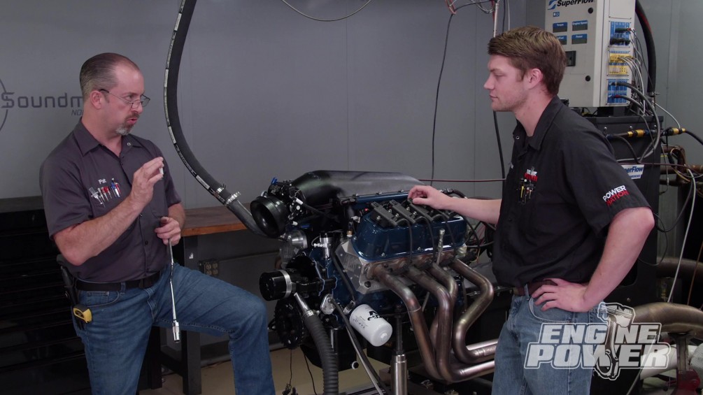
(Frankie)>> With a hi-ram intake manifold, a Coil-Near-Plug ignition system, and a Ford blue paint job this engine has the style it takes to turn some heads.
(Pat)>> And the guts it needs to make big power in the dyno cell. ♪ ♪
(Frankie)>> Welcome to Engine Power. Today is a great day because we are gonna be wrapping up our 410 cubic inch stroked Windsor that you can enter to win. This engine has a ton of great parts and a lot of hard work put into it, but before we go any further we want to make sure you're caught up. And you know what that means!
(Pat)>> Flashback!
(Frankie)>> After thoroughly prepping and cleaning the block we checked the clearances. Since this is a high performance engine ring gap was opened up to 24 thousandths on the top ring and 26 thousandths on the second ring. Then we installed an Eagle 43-40 forged crankshaft with a four inch stroke followed by a Comp hydraulic roller cam.
(Pat)>> Mahle 26-18 forged pistons and Eagle H-beam rods completed the rotating assembly. We've sprayed Ford blue engine enamel on the block, and for the ultimate in accuracy we installed a Holley EFI crank trigger system. Finally, we torqued down a set of AFR 220cc c-n-c ported cylinder heads with a 58cc combustion chamber.
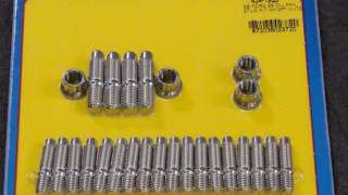
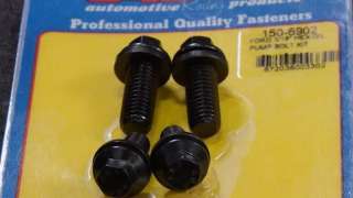
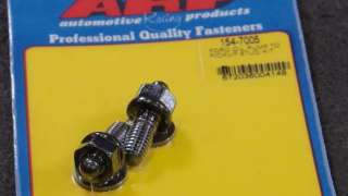
(Frankie)>> The first thing we're gonna tackle on our 410 Windsor is sealing up the oiling system, and that means getting our high volume oil pump, our pick-up, and our pan installed, and to do that we're gonna use ARP fasteners. ARP makes a bunch of specific fastener kits for different engines, parts, and in a variety of finishes for your specific application. For our engine we're gonna be using their six point oil pump bolt kit, opting for their oil pick-up stud kit, and using the nut that came with our main bolt kit to fasten the pick-up to the mains. When we go to put the pan on, we'll be using one of their 12-point stainless oil pan stud kits. Not only are these going to look great, but it's also gonna make it that much easier to put the oil pan on. With such a wide variety of kits it's pretty easy to find quality fasteners for your engine from top to bottom. We're also going to be using an ARP chro-moly oil pump driveshaft. It's a considerable upgrade from the o-e-m hex driveshaft that this engine would have come with. Since this will most likely be a street engine, we opted for a Melling high volume oil pump from Summit Racing. It's torqued to 45-pound feet. The pick-up we're using comes with the Weiand oil pan kit and is matched to the shape and depth of the pan. ♪ ♪ To keep them securely in place thread locker goes on one end of the studs and they're screwed into the block. We prefer studs instead of bolts for this application. They make it much easier to properly locate the gasket and pan.
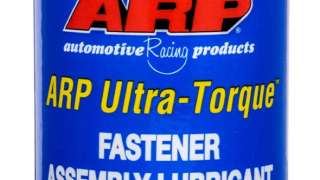
(Pat)>> We'll verify the distance between the pick-up and the bottom of the pan using our Goodson straight edge. We've got 250 thousandths clearance, which is right in spec. Black r-t-v is sparingly added to the parting lines and in the corners before installing the gasket that comes with the oil pan kit. Before everything gets sealed up, we'll spray some valvetrain lube on the timing set. The Weiand pan has a seven quart capacity and is made for swapping a 351 Windsor into a '79 through '93 Mustang. The studs receive ARP Ultra Torque and are tightened down to the compression stops of the gasket. The lifter bores and the lifters themselves receive break-in oil. These are Comp Cams' short travel extreme duty retrofit hydraulic rollers that have been rim polished.
(Frankie)>> In order to align them we'll temporarily install the guide plates and rocker studs that came with our AFR heads. We'll also mock-up the push rods and rockers, centering the rocker tips on the valve stems. After tightening the rocker studs the rockers and push rods are removed so the guide plates can be tacked together. ♪ ♪ Finally, the rocker studs are removed one at a time, receive some thread sealer, and are torqued to 55-pound feet.
(Pat)>> After cleaning up our Comp 7.850 long push rods we'll apply extreme pressure lube and slide them into place. It's also applied to the other end, the rocker stud threads, and the valve stem tips. ♪ ♪ The rockers are Comp Ultra Pro Magnum XDs with a 1.7 ratio and a full roller body. They're installed on t-d-c compression of each cylinder in the firing order. Pre-load is set to one-eighth turn past zero lash. The poly locks are then torqued to 20-pound feet.
(Frankie)>> How do you spell e-f-i?
(Pat)>> H-o-l-l-e-y!
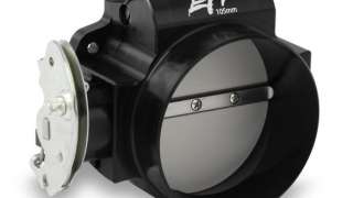
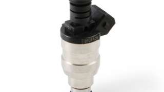
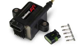
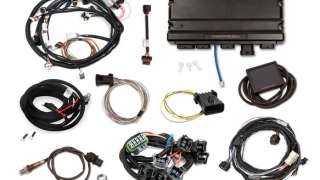
(Frankie)>> Now that we've got our valve train installed the next step is gonna be putting on the intake manifold, and for that we thought I'd be a great time to talk about the e-f-i selection we're gonna use on this engine. It all starts with this Holley hi-ram small block Ford intake manifold and one of their 105-millimeter throttle body tops. We painted this one matte black, and we've color matched our fuel rails to give it a little extra pizzaz. It's all gonna be filled out with a Scott Drake billet aluminum water neck, a set of 48 pound per hour Holley injectors, Holley e-f-i's 105-millimeter throttle body with low r-p-m taper, and Holley EFI sensors throughout. To pair with our 36 minus 1 crank trigger that's already on our engine, instead of a distributor we're gonna go with an MSD cam sync along with the ignition adapter harness for or unit. This is going to allow us to run one of the coolest systems on this engine, the Coil-Near-Plug ignition. For that we're gonna be using Holley EFI's Smart Coil conversion kit along with their LS coil relocation brackets that we've prepped because we're going to weld them directly to the top of these Mister Gasket polished cast aluminum valve covers. And then when we're done, we'll paint them our conventional color, Ford blue. These not only look awesome, but they give us individual cylinder ignition control, and allow the coils to have a longer saturation time before firing. It's all going to be controlled with a Holley Terminator-X Max e-c-u. These units are extremely easy to use, and they even come with a three and a half inch touch screen to do all the setup and tuning. Or if you want to get a little bit deeper in the tune-up you can use Holley's free laptop software. They come with four programmable inputs and four programmable outputs, and even a one bar internal map sensor for n/a applications. You can switch it to an external map sensor, and the unit has integrated boost and nitrous control for your power adder of choice. There's a lot of great parts on this table but we've got to get them installed one by one and we'll be that much closer to dynoing this bad boy. Up next, we break out the welder and the paint gun to give the Windsor some custom touches.
(Pat)>> Then it's dyno time!
(Pat)>> We're using an ARP 87-40 intake stud kit for the Windsor. This makes it much easier to align the gaskets and the intake manifold during installation. These Fel Pro gaskets are recommended by AFR. We applied some weatherstrip adhesive to the back of them to keep them in place. We'll apply some black silicone where the block meets the head to prevent oil seepage, and a thin bead around the water ports to help them seal up.
(Frankie)>> With a glorious bead along each China wall the intake manifold drops on and we'll check the intake port alignment. Once we're happy we'll slowly and evenly tighten it down rechecking as we go. ♪ ♪ The intake top is held on with 12-point ARP stainless steel bolts that are torqued to 110-pound inches. ♪ ♪ We'll fill the injector bungs with Holley's 48 pound per hour EV-1 style injectors. We'll seal up the intake tract with our LS style throttle body, and bolt on the Scott Drake billet aluminum water neck. ♪ ♪
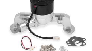
(Pat)>> Since we don't know what application this engine will go in we're going to install a Frostbite electric water pump, which we will use in the dyno cell. Now comes the fun part. Some good ole fashioned fabrication using slightly modified LS coil relocation brackets. We'll get it centered on the Mister Gasket cast aluminum valve covers and mark the location before it's tacked in place. The valve covers are prepped with an abrasive disc, cleaned with lacquer thinner, and the brackets are tacked in multiple places. These aren't structural welds. So, a few beads will suffice. ♪ ♪
(Frankie)>> To prep them for paint the welds get a quick scrub with a stainless steel brush, and the valve covers are hit with a red scuff pad. Then they're washed with warm soapy water, rinsed, and blown dry. The valve covers get the same treatment as the block. After primer a light coat for good coverage, and a few heavy coats for a glossy finish. [ paint gun hissing ]
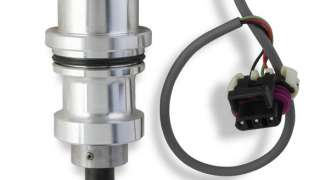
(Pat)>> We'll apply a generous coat of valve train lube, bolt down the valve covers, and install the breathers. ♪ ♪ The Holley Smart Coils are designed to run directly off the Terminator-X system. No coil drivers are needed. These are ready to handle an intense amount of horsepower. So, they're more than enough for our Windsor. After the spark plugs are in, we'll install adapter plates to use our dyno headers. These have a one and seven-eighths to two inch stepped primary and a three inch collector.
(Frankie)>> For our custom setup we're gonna build some custom wires out of this Holley EFI universal wire set. For a clean look we'll build the spark plug wires to just the right length. Once they're marked, they are cut, stripped, and the terminal is crimped on. We'll grease the boot and the terminal so the boot slips on easily. ♪ ♪
(Pat)>> Up next, we do some wiring mods to make our Coil-Near-Plug ignition run smooth as glass in the dyno cell.
(Frankie)>> Since we're talking so much about e-f-i we thought it'd be a great time to talk about some of the more common sensors you'll see in an engine, and how they work in today's tech tip. The first type measures rotational speed and position, and the one you're more commonly familiar with is probably a magnetic pulse generator, or magnetic pick-up sensor. This sensor has two wires, and when a magnetic trigger passes in front of it, it creates an alternating current signal. These are relatively simple because if the trigger is within range and the sensor is working it will create an alternating current. The next type is a hall-effect sensor, which is a little bit more accurate than a magnetic pick-up. This sensor still uses a magnetic trigger, but it has three wires. A five-volt reference in, a ground, and a sensor wire that outputs a five-volt digital d/c signal that goes from zero volts straight to five volts and back to zero. This makes it a lot more accurate, and it's generally used on e-f-i applications. If you're not measuring rotational speed but are measuring position more than likely it's using a potentiometer. This sensor uses three wires. A five volt reference in, a ground, and a sensor signal wire that outputs an analog d/c signal that goes between just above zero and just below five volts as the resistance varies inside the sensor with rotation. A critical component of engine operation is measuring various pressures like oil and fuel pressure, and to do that we're gonna use a pressure transducer. These use three wires. They have a five-volt reference in, a ground, and a sensor signal wire that outputs a d/c analog signal between just above zero and just below five volts as the resistance changes when pressure is applied. Just as important as pressures is temperatures, and for that we'll use a thermistor. There's two types. A positive type, which increases resistance as temperature increases, and negative type, which decreases resistance as temperature increases. The old style of thermistor generally had one wire going in that came directly from a gauge and used the engine as a ground. This means that the contact between the threads of the sensor and whatever it's going into are very important for sensor operation. A modern type has two wires. One that sends a signal to the e-c-u and one that operates as a sensor ground. This means that the sensor should operate as long as it is plugged in. These are just some of the common types of sensors but there are a lot more you can run into on an engine. Hopefully, this gives you a good indication of how they work, but if you need help finding a replacement for yours you can talk to the experts at Summit Racing Equipment. We'll fill out our engine sensors with a throttle position sensor from Holley along with their coolant temperature sensor. In order to run the Coil-Near-Plug setup we have to modify the Terminator-X main harness. First the loom is removed. Then the new wires are added and taped to the existing harness. Each new wire is then cut, stripped, crimped, and put in the correct pin in the e-c-u connector. It seems a bit intimidating, but the included wiring diagram makes it simple. Finally, we can put the loom back on, tape everything up, and hook it up for good. ♪ ♪
Once the wiring is complete, we'll setup the dyno throttle linkage. Up next, with e-f-i this powerful it's easy to get the Windsor dialed in to perfection!
(Frankie)>> The last thing we need to do before we can start our engine is configure the ignition system in the Holley EFI software. The software makes it really easy. We just have to select our 36 minus 1 crank trigger as the crank sensor and choose a single pulse input for our cam sync. We'll change the output to coil on plug and we're ready to go.
(Pat)>> I feel like we're in the space shuttle because there's computers and displays, which I like.
(Frankie)>> I'm excited!
(Pat)>> I'm very excited.
(Frankie)>> This is just cool, I think. Putting a bunch of new technology on a little bit of an older engine and just having the ability to do that I think is really cool. [ engine starting ]
(Frankie)>> See! That's nice, and the great thing about these systems is that the idle and drivability stuff, the more it runs and the more it sees those conditions the more it's gonna learn. Once it gets up to temp, and starts learning, and just gets better and better from there.
(Pat)>> The display on a Terminator-X is big.
(Frankie)>> Having that Pro dash is really nice cause then you can just have a gauge that comes right up.
(Pat)>> Let's see what 410 inches of Windsor sounds like with coil on, coil near plug, what do they call it?
(Frankie)>> Coil-Near-Plug. [ engine revving ]
(Pat)>> 463-pound feet of torque, 434 horse. I am happy with the oil pressure. The fuel pressure looks good.
(Frankie)>> AFRs are right on target.
(Pat)>> Let's make a full pull. Turn the r-p-ms up a little bit. [ engine revving ]
(Pat)>> Clean right through the pull.
(Frankie)>> Sounded good, looked good.
(Pat)>> It's gonna need some tuning though. We'll take that. It's 460-pound feet of torque, 493 horse. It doesn't matter what engine it is. What's your first order of business on tuning?
(Frankie)>> Timing.
(Pat)>> I agree with that because timing has a huge effect on it obviously, and that directly affects your air/fuel. So, you time for torque and you jet for horsepower. We have electronical jets on this one.
(Frankie)>> We're at 30 degrees of timing now.
(Pat)>> That's gonna be nowhere near enough. I would make a big swing at that one. I would put at least 4 or 5 degrees in it.
(Frankie)>> We'll just put 5 in it and make it 35. Let me do that. It's running great, looks great!
(Pat)>> It's sexy! I really like it!
(Frankie)>> Can you say that on t-v?
(Pat)>> I just did. [ engine revving ]
(Pat)>> Clean, clean, 476-pound feet. That's a jump, and 522 horse pressures.
(Frankie)>> I like how it smoothed out the graph too, which we've seen every time. It makes it a little bit smoother. Put a little bit more in it. We'll go two degrees.
(Pat)>> Two degrees of timing in it. Done?
(Frankie)>> Yep!
(Pat)>> It's just that easy.
(Frankie)>> Click, click, and bam. [ engine revving ]
(Pat)>> That's 481.7-pound feet of torque, 526.8 horsepower. Look how nice that looks. I like it when the graph is doing what it's supposed to. If this was a carburetor now we'd start pulling jet because O-2 wise there's no way in the pit of hades this thing should run that rich on pump gas. So, let's peel some fuel out of it. I would say let's set a target air/fuel of 13-3, 13-4. Somewhere in there. We were at 12-5, that's almost a full point.
(Frankie)>> Relatively large leap.
(Pat)>> That's a relatively large amount of fuel but it has a relatively large amount of fuel going through it. If you're familiar with the combination, just because it's got fuel injection on it doesn't mean you're gonna do anything inherently very much different.
(Frankie)>> And because we have a dyno, we can do this in a controlled manner. If you were doing this in a car you were driving down the street that's a little different, but we can do this.
(Pat)>> Let's let her rip and see what she does here. [ engine revving ]
(Pat)>> It's already gonna be really better. [ engine revving ]
[ Frankie whistles ]
(Pat)>> That was very, very, very good!
(Frankie)>> Big change, big jump!
(Pat)>> 562 horse, 504-pound feet.
(Frankie)>> The crazy part is that everywhere on the graph for torque it makes 450 or over. That's a great curve! Let's pull a plug and go from there.
(Pat)>> The ever so slight tan color of the porcelain indicates that our air/fuel mix looks safe for our pump gas tune-up. Our choice of timing looks dead on for this power level. By the way the tune-up looks on the screen and by the way an old school guy looks at a plug for a tune-up I think we're gonna leave this one right where it is.
(Frankie)>> We don't normally do this a lot, putting some high tech stuff on an old school workhorse, but using Holley EFI, the Coil-Near-Plug conversion, and the port fuel injection is really easy to do. And I agree, I think whatever this goes into it's gonna be really nice.
(Pat)>> New tech for an old school workhorse.
(Frankie)>> Like him.
(Pat)>> What? If you want to see more cool tech and more cool builds be sure to check out our website.
Show Full Transcript
(Frankie)>> With a hi-ram intake manifold, a Coil-Near-Plug ignition system, and a Ford blue paint job this engine has the style it takes to turn some heads.
(Pat)>> And the guts it needs to make big power in the dyno cell. ♪ ♪
(Frankie)>> Welcome to Engine Power. Today is a great day because we are gonna be wrapping up our 410 cubic inch stroked Windsor that you can enter to win. This engine has a ton of great parts and a lot of hard work put into it, but before we go any further we want to make sure you're caught up. And you know what that means!
(Pat)>> Flashback!
(Frankie)>> After thoroughly prepping and cleaning the block we checked the clearances. Since this is a high performance engine ring gap was opened up to 24 thousandths on the top ring and 26 thousandths on the second ring. Then we installed an Eagle 43-40 forged crankshaft with a four inch stroke followed by a Comp hydraulic roller cam.
(Pat)>> Mahle 26-18 forged pistons and Eagle H-beam rods completed the rotating assembly. We've sprayed Ford blue engine enamel on the block, and for the ultimate in accuracy we installed a Holley EFI crank trigger system. Finally, we torqued down a set of AFR 220cc c-n-c ported cylinder heads with a 58cc combustion chamber.
(Frankie)>> The first thing we're gonna tackle on our 410 Windsor is sealing up the oiling system, and that means getting our high volume oil pump, our pick-up, and our pan installed, and to do that we're gonna use ARP fasteners. ARP makes a bunch of specific fastener kits for different engines, parts, and in a variety of finishes for your specific application. For our engine we're gonna be using their six point oil pump bolt kit, opting for their oil pick-up stud kit, and using the nut that came with our main bolt kit to fasten the pick-up to the mains. When we go to put the pan on, we'll be using one of their 12-point stainless oil pan stud kits. Not only are these going to look great, but it's also gonna make it that much easier to put the oil pan on. With such a wide variety of kits it's pretty easy to find quality fasteners for your engine from top to bottom. We're also going to be using an ARP chro-moly oil pump driveshaft. It's a considerable upgrade from the o-e-m hex driveshaft that this engine would have come with. Since this will most likely be a street engine, we opted for a Melling high volume oil pump from Summit Racing. It's torqued to 45-pound feet. The pick-up we're using comes with the Weiand oil pan kit and is matched to the shape and depth of the pan. ♪ ♪ To keep them securely in place thread locker goes on one end of the studs and they're screwed into the block. We prefer studs instead of bolts for this application. They make it much easier to properly locate the gasket and pan.
(Pat)>> We'll verify the distance between the pick-up and the bottom of the pan using our Goodson straight edge. We've got 250 thousandths clearance, which is right in spec. Black r-t-v is sparingly added to the parting lines and in the corners before installing the gasket that comes with the oil pan kit. Before everything gets sealed up, we'll spray some valvetrain lube on the timing set. The Weiand pan has a seven quart capacity and is made for swapping a 351 Windsor into a '79 through '93 Mustang. The studs receive ARP Ultra Torque and are tightened down to the compression stops of the gasket. The lifter bores and the lifters themselves receive break-in oil. These are Comp Cams' short travel extreme duty retrofit hydraulic rollers that have been rim polished.
(Frankie)>> In order to align them we'll temporarily install the guide plates and rocker studs that came with our AFR heads. We'll also mock-up the push rods and rockers, centering the rocker tips on the valve stems. After tightening the rocker studs the rockers and push rods are removed so the guide plates can be tacked together. ♪ ♪ Finally, the rocker studs are removed one at a time, receive some thread sealer, and are torqued to 55-pound feet.
(Pat)>> After cleaning up our Comp 7.850 long push rods we'll apply extreme pressure lube and slide them into place. It's also applied to the other end, the rocker stud threads, and the valve stem tips. ♪ ♪ The rockers are Comp Ultra Pro Magnum XDs with a 1.7 ratio and a full roller body. They're installed on t-d-c compression of each cylinder in the firing order. Pre-load is set to one-eighth turn past zero lash. The poly locks are then torqued to 20-pound feet.
(Frankie)>> How do you spell e-f-i?
(Pat)>> H-o-l-l-e-y!
(Frankie)>> Now that we've got our valve train installed the next step is gonna be putting on the intake manifold, and for that we thought I'd be a great time to talk about the e-f-i selection we're gonna use on this engine. It all starts with this Holley hi-ram small block Ford intake manifold and one of their 105-millimeter throttle body tops. We painted this one matte black, and we've color matched our fuel rails to give it a little extra pizzaz. It's all gonna be filled out with a Scott Drake billet aluminum water neck, a set of 48 pound per hour Holley injectors, Holley e-f-i's 105-millimeter throttle body with low r-p-m taper, and Holley EFI sensors throughout. To pair with our 36 minus 1 crank trigger that's already on our engine, instead of a distributor we're gonna go with an MSD cam sync along with the ignition adapter harness for or unit. This is going to allow us to run one of the coolest systems on this engine, the Coil-Near-Plug ignition. For that we're gonna be using Holley EFI's Smart Coil conversion kit along with their LS coil relocation brackets that we've prepped because we're going to weld them directly to the top of these Mister Gasket polished cast aluminum valve covers. And then when we're done, we'll paint them our conventional color, Ford blue. These not only look awesome, but they give us individual cylinder ignition control, and allow the coils to have a longer saturation time before firing. It's all going to be controlled with a Holley Terminator-X Max e-c-u. These units are extremely easy to use, and they even come with a three and a half inch touch screen to do all the setup and tuning. Or if you want to get a little bit deeper in the tune-up you can use Holley's free laptop software. They come with four programmable inputs and four programmable outputs, and even a one bar internal map sensor for n/a applications. You can switch it to an external map sensor, and the unit has integrated boost and nitrous control for your power adder of choice. There's a lot of great parts on this table but we've got to get them installed one by one and we'll be that much closer to dynoing this bad boy. Up next, we break out the welder and the paint gun to give the Windsor some custom touches.
(Pat)>> Then it's dyno time!
(Pat)>> We're using an ARP 87-40 intake stud kit for the Windsor. This makes it much easier to align the gaskets and the intake manifold during installation. These Fel Pro gaskets are recommended by AFR. We applied some weatherstrip adhesive to the back of them to keep them in place. We'll apply some black silicone where the block meets the head to prevent oil seepage, and a thin bead around the water ports to help them seal up.
(Frankie)>> With a glorious bead along each China wall the intake manifold drops on and we'll check the intake port alignment. Once we're happy we'll slowly and evenly tighten it down rechecking as we go. ♪ ♪ The intake top is held on with 12-point ARP stainless steel bolts that are torqued to 110-pound inches. ♪ ♪ We'll fill the injector bungs with Holley's 48 pound per hour EV-1 style injectors. We'll seal up the intake tract with our LS style throttle body, and bolt on the Scott Drake billet aluminum water neck. ♪ ♪
(Pat)>> Since we don't know what application this engine will go in we're going to install a Frostbite electric water pump, which we will use in the dyno cell. Now comes the fun part. Some good ole fashioned fabrication using slightly modified LS coil relocation brackets. We'll get it centered on the Mister Gasket cast aluminum valve covers and mark the location before it's tacked in place. The valve covers are prepped with an abrasive disc, cleaned with lacquer thinner, and the brackets are tacked in multiple places. These aren't structural welds. So, a few beads will suffice. ♪ ♪
(Frankie)>> To prep them for paint the welds get a quick scrub with a stainless steel brush, and the valve covers are hit with a red scuff pad. Then they're washed with warm soapy water, rinsed, and blown dry. The valve covers get the same treatment as the block. After primer a light coat for good coverage, and a few heavy coats for a glossy finish. [ paint gun hissing ]
(Pat)>> We'll apply a generous coat of valve train lube, bolt down the valve covers, and install the breathers. ♪ ♪ The Holley Smart Coils are designed to run directly off the Terminator-X system. No coil drivers are needed. These are ready to handle an intense amount of horsepower. So, they're more than enough for our Windsor. After the spark plugs are in, we'll install adapter plates to use our dyno headers. These have a one and seven-eighths to two inch stepped primary and a three inch collector.
(Frankie)>> For our custom setup we're gonna build some custom wires out of this Holley EFI universal wire set. For a clean look we'll build the spark plug wires to just the right length. Once they're marked, they are cut, stripped, and the terminal is crimped on. We'll grease the boot and the terminal so the boot slips on easily. ♪ ♪
(Pat)>> Up next, we do some wiring mods to make our Coil-Near-Plug ignition run smooth as glass in the dyno cell.
(Frankie)>> Since we're talking so much about e-f-i we thought it'd be a great time to talk about some of the more common sensors you'll see in an engine, and how they work in today's tech tip. The first type measures rotational speed and position, and the one you're more commonly familiar with is probably a magnetic pulse generator, or magnetic pick-up sensor. This sensor has two wires, and when a magnetic trigger passes in front of it, it creates an alternating current signal. These are relatively simple because if the trigger is within range and the sensor is working it will create an alternating current. The next type is a hall-effect sensor, which is a little bit more accurate than a magnetic pick-up. This sensor still uses a magnetic trigger, but it has three wires. A five-volt reference in, a ground, and a sensor wire that outputs a five-volt digital d/c signal that goes from zero volts straight to five volts and back to zero. This makes it a lot more accurate, and it's generally used on e-f-i applications. If you're not measuring rotational speed but are measuring position more than likely it's using a potentiometer. This sensor uses three wires. A five volt reference in, a ground, and a sensor signal wire that outputs an analog d/c signal that goes between just above zero and just below five volts as the resistance varies inside the sensor with rotation. A critical component of engine operation is measuring various pressures like oil and fuel pressure, and to do that we're gonna use a pressure transducer. These use three wires. They have a five-volt reference in, a ground, and a sensor signal wire that outputs a d/c analog signal between just above zero and just below five volts as the resistance changes when pressure is applied. Just as important as pressures is temperatures, and for that we'll use a thermistor. There's two types. A positive type, which increases resistance as temperature increases, and negative type, which decreases resistance as temperature increases. The old style of thermistor generally had one wire going in that came directly from a gauge and used the engine as a ground. This means that the contact between the threads of the sensor and whatever it's going into are very important for sensor operation. A modern type has two wires. One that sends a signal to the e-c-u and one that operates as a sensor ground. This means that the sensor should operate as long as it is plugged in. These are just some of the common types of sensors but there are a lot more you can run into on an engine. Hopefully, this gives you a good indication of how they work, but if you need help finding a replacement for yours you can talk to the experts at Summit Racing Equipment. We'll fill out our engine sensors with a throttle position sensor from Holley along with their coolant temperature sensor. In order to run the Coil-Near-Plug setup we have to modify the Terminator-X main harness. First the loom is removed. Then the new wires are added and taped to the existing harness. Each new wire is then cut, stripped, crimped, and put in the correct pin in the e-c-u connector. It seems a bit intimidating, but the included wiring diagram makes it simple. Finally, we can put the loom back on, tape everything up, and hook it up for good. ♪ ♪
Once the wiring is complete, we'll setup the dyno throttle linkage. Up next, with e-f-i this powerful it's easy to get the Windsor dialed in to perfection!
(Frankie)>> The last thing we need to do before we can start our engine is configure the ignition system in the Holley EFI software. The software makes it really easy. We just have to select our 36 minus 1 crank trigger as the crank sensor and choose a single pulse input for our cam sync. We'll change the output to coil on plug and we're ready to go.
(Pat)>> I feel like we're in the space shuttle because there's computers and displays, which I like.
(Frankie)>> I'm excited!
(Pat)>> I'm very excited.
(Frankie)>> This is just cool, I think. Putting a bunch of new technology on a little bit of an older engine and just having the ability to do that I think is really cool. [ engine starting ]
(Frankie)>> See! That's nice, and the great thing about these systems is that the idle and drivability stuff, the more it runs and the more it sees those conditions the more it's gonna learn. Once it gets up to temp, and starts learning, and just gets better and better from there.
(Pat)>> The display on a Terminator-X is big.
(Frankie)>> Having that Pro dash is really nice cause then you can just have a gauge that comes right up.
(Pat)>> Let's see what 410 inches of Windsor sounds like with coil on, coil near plug, what do they call it?
(Frankie)>> Coil-Near-Plug. [ engine revving ]
(Pat)>> 463-pound feet of torque, 434 horse. I am happy with the oil pressure. The fuel pressure looks good.
(Frankie)>> AFRs are right on target.
(Pat)>> Let's make a full pull. Turn the r-p-ms up a little bit. [ engine revving ]
(Pat)>> Clean right through the pull.
(Frankie)>> Sounded good, looked good.
(Pat)>> It's gonna need some tuning though. We'll take that. It's 460-pound feet of torque, 493 horse. It doesn't matter what engine it is. What's your first order of business on tuning?
(Frankie)>> Timing.
(Pat)>> I agree with that because timing has a huge effect on it obviously, and that directly affects your air/fuel. So, you time for torque and you jet for horsepower. We have electronical jets on this one.
(Frankie)>> We're at 30 degrees of timing now.
(Pat)>> That's gonna be nowhere near enough. I would make a big swing at that one. I would put at least 4 or 5 degrees in it.
(Frankie)>> We'll just put 5 in it and make it 35. Let me do that. It's running great, looks great!
(Pat)>> It's sexy! I really like it!
(Frankie)>> Can you say that on t-v?
(Pat)>> I just did. [ engine revving ]
(Pat)>> Clean, clean, 476-pound feet. That's a jump, and 522 horse pressures.
(Frankie)>> I like how it smoothed out the graph too, which we've seen every time. It makes it a little bit smoother. Put a little bit more in it. We'll go two degrees.
(Pat)>> Two degrees of timing in it. Done?
(Frankie)>> Yep!
(Pat)>> It's just that easy.
(Frankie)>> Click, click, and bam. [ engine revving ]
(Pat)>> That's 481.7-pound feet of torque, 526.8 horsepower. Look how nice that looks. I like it when the graph is doing what it's supposed to. If this was a carburetor now we'd start pulling jet because O-2 wise there's no way in the pit of hades this thing should run that rich on pump gas. So, let's peel some fuel out of it. I would say let's set a target air/fuel of 13-3, 13-4. Somewhere in there. We were at 12-5, that's almost a full point.
(Frankie)>> Relatively large leap.
(Pat)>> That's a relatively large amount of fuel but it has a relatively large amount of fuel going through it. If you're familiar with the combination, just because it's got fuel injection on it doesn't mean you're gonna do anything inherently very much different.
(Frankie)>> And because we have a dyno, we can do this in a controlled manner. If you were doing this in a car you were driving down the street that's a little different, but we can do this.
(Pat)>> Let's let her rip and see what she does here. [ engine revving ]
(Pat)>> It's already gonna be really better. [ engine revving ]
[ Frankie whistles ]
(Pat)>> That was very, very, very good!
(Frankie)>> Big change, big jump!
(Pat)>> 562 horse, 504-pound feet.
(Frankie)>> The crazy part is that everywhere on the graph for torque it makes 450 or over. That's a great curve! Let's pull a plug and go from there.
(Pat)>> The ever so slight tan color of the porcelain indicates that our air/fuel mix looks safe for our pump gas tune-up. Our choice of timing looks dead on for this power level. By the way the tune-up looks on the screen and by the way an old school guy looks at a plug for a tune-up I think we're gonna leave this one right where it is.
(Frankie)>> We don't normally do this a lot, putting some high tech stuff on an old school workhorse, but using Holley EFI, the Coil-Near-Plug conversion, and the port fuel injection is really easy to do. And I agree, I think whatever this goes into it's gonna be really nice.
(Pat)>> New tech for an old school workhorse.
(Frankie)>> Like him.
(Pat)>> What? If you want to see more cool tech and more cool builds be sure to check out our website.
