Engine Power Featured Projects
Engine Power Builds
Want more content like this?
Join the PowerNation Email NewsletterParts Used In This Episode
Shacklett Automotive Machine
Shacklett Automotive Machine
Sunnen Products Company
Sunnen Dial Bore Gauge
The Industrial Depot
Tools, Hardware, Shop Supplies
Episode Transcript
(Pat)>> You're watching Powernation!
(Pat)>> Today on Engine Power we're building a winning Windsor, and the best part about it is, well you'll just have to watch to find out. [ Music ]
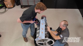
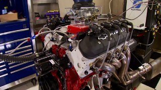
(Pat)>> Hi everyone, and welcome to Engine Power. We are very excited to start a brand new project for you. We've done a few Chevys and even a small block Mopar, but today it is all about Ford power. These are the makings of a 410 cubic inch stroker small block Windsor. This is gonna be a heavy hitter on pump gas, but what makes all this extra special is we have partnered up with Holley so you can enter to win this exact engine for yourself.
(Frankie)>> And that's really exciting for one of you because this engine is gonna come with a bunch of great parts, including a fully forged rotating assembly with Eagle crank and rods and a Mahle piston, a set of AFR 220 competition ported cylinder heads, a Holley hi-ram intake manifold with their 105 millimeter throttle body intake top, and the whole engine will be controlled with Holley e-f-i, including their Terminator-X Max and their Smart Coil Kit. But before we can get all of this in there and get it in one of your driveways we have a lot of work to do, including some block prep.
(Pat)>> A bunch of that!
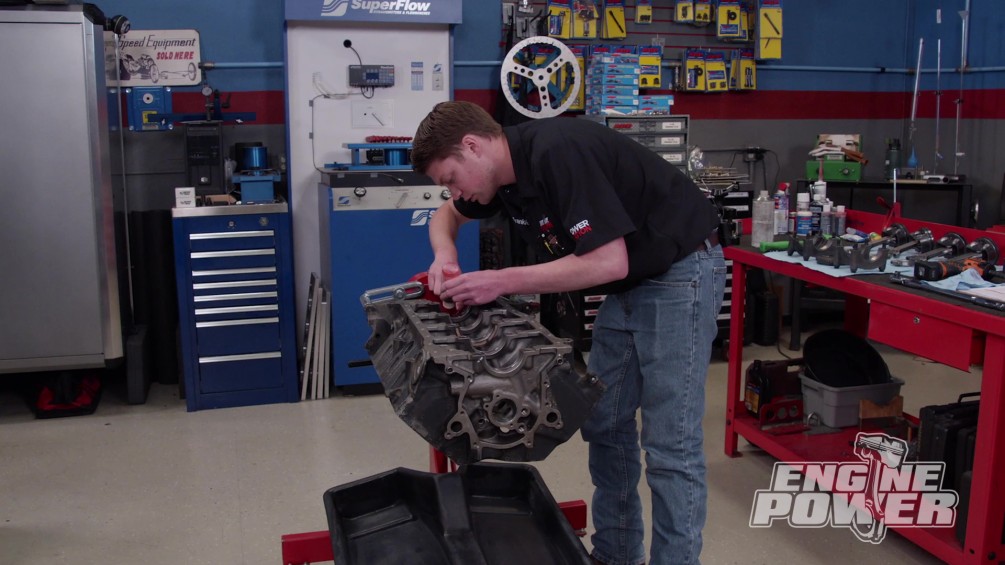
(Frankie)>> Let's get started. [ Music ] First up is removing the threaded oil gallery plugs throughout the block. This will allow us to drive out the pressed in plugs in the front of the engine. We'll do this with a long piece of threaded rod and a hammer. To remove the plug from the lifter gallery crossover port we'll drill a pilot hole, run in a self tapping screw, and use a slide hammer to pop it out. [ Music ] Next, we'll port the oil inlet from the pump using the gasket as a template. A series of carbide burrs and a light touch gets the job done safely. [ Music ] It's important to go slowly and check your work. We say it often but it bears repeating. It's easier to remove more material but very hard to put it back. Throughout the process we'll continue to use the gasket as a guide. [ air tool humming ]
(Frankie)>> To further smooth out the finish a cartridge roll comes next. [ air tool buzzing ]
(Frankie)>> Once we're happy with the surface we'll follow the oil's path, smoothing as we go. [ air tool buzzing ] [ Music ]
(Frankie)>> It's important to have a wide variety of carbide shapes and sizes to get into all the block's nooks and crannies.
(Pat)>> Moving on, we'll tune up the drain backs in the lifter valley. Notice that the burr is running at moderate speed. This helps maintain control and not move too fast. We'll give the same treatment to the pressurized oil crossover for the lifters. [ Music ] We are tapping the oil galleries that had press in plugs in favor of threaded pipe plugs. This serves a couple of different purposes. First the plug cannot pop out under pressure unlike a pressed in one. Second, it makes the oil galleries easily serviceable since we can readily remove and reuse the plug. The holes are tapped so the plug is just under flush from the surface because if you go too deep you can potentially block off another oil gallery. [ Music ] Once we're happy with the fit we'll chamfer the outside. Every bolt hole is finished with a light chamfer. [ drill humming ]
(Frankie)>> There are several reasons to deburr a block, which we'll get to in a minute, but the one that is my favorite is that it stops the paper shop towels from tearing when you're wiping off the engine. [ Music ]
(Pat)>> Oh yeah, very nice hustle on this one.
(Frankie)>> It wasn't too bad. A couple of hours into it, but the great part is that this block is definitely gonna benefit from this.
(Pat)>> I would agree with that. Now this seems like a tedious task, but this can benefit any engine that you work on. I don't care what it is. Smooth oil flow is always a great thing and working with a block that you can cut yourself, and deburring it eliminates places for stress risers to start. So, whoever gets this one's gonna get a nice piece. What's next?
(Frankie)>> We've got to clean it. I'm pretty much done here. It's all deburred. The oil returns are all smoothed out. All the pressure ports are all smooth out. So, I've got to get this in the cleaner, get the bores clean, get all the oil galleries clean, and then we can move on to assembly.
(Pat)>> To the cleaner! Bring it with you!
(Frankie)>> It's oil galleries, not galley. A galley's a kitchen on a ship.
(Pat)>> Yeah! [ Music ] Our jet washer runs at 150 degrees. So, we'll use it to wash the block for about 30 to 40 minutes. [ Music ]
(Frankie)>> Up next, they may be small but piston rings can have a big impact on your engine's performance.
(Pat)>> With Frankie's enthusiastic and strangely cheerful help assembly of the 410-inch Windsor begins. To ensure that the cap is aligned and the bolts won't bind up in the bolt holes we start by gently running down the fasteners, and then we cap the main with a dead blow hammer to seat it. Now the bolts can be snugged down and torqued to a final value of 100-pound feet. The crankshaft journal is precisely measured with a micrometer, and that measurement is transferred to our Sunnen dial bore gauge. [ Music ] With the bearings installed the housing bore is measured to determine its vertical oil clearance. Number five main measures right at three thousandths, which is technically one ten-thousandths above the stock spec, but for our high performance engine it will work great. [ torque wrench clicking ]
(Pat)>> As always, we do this for every housing bore. [ Music ] The same process is done for each individual connecting rod. We'll measure the journal, transfer the measurement to the dial bore gauge, and check the rod. They all came in between 22 and 24 ten-thousandths, excellent! [ grinder buzzing ]
(Pat)>> Accuracy of the ring gap is important, and it depends on what the engine is used for. As an engine builder you determine what ring gap fits your needs. Since this is a high performance engine that will definitely see some abuse, the ring gaps are opened up to 24 thousandths on the top ring and 26 thousandths on the second ring. [ grinder buzzing ]
(Pat)>> We always gap the second compression ring first. For one, the second ring is usually gapped a little bigger. Plus, this gives you the time to dial everything in perfectly for that ultra critical top ring gap. After gapping 16 rings you'll be glad it's over, but you'll be even happier that the job is done to your liking. The right tools, like this Summit Racing ring squaring tool, helps you be consistent and accurate. [ Music ] Putting piston assemblies together is not hard, but it can be a bit challenging to install the lock. Fortunately, these locks are a solid piece of round wire instead of a spiral lock. So, they go in a bit easier. The pistons are a Mahle Power Pack Kit forged from 26-18 alloy. They have a one millimeter, one millimeter, two millimeter ring pack, 927 thousandths heavy duty wrist pins, a 20cc effective dish volume, and they are phosphate coated with a graphal anti-friction coating on the skirts. We are almost ready to start assembling our stroker Windsor, but before we do that I'd like to stop and take a little bit of time to talk about something that's very important for engine operation, and that is piston ring tension. Why, because the ring tension is a big player in friction in the engine, and the more friction we can reduce, still control oil and seal combustion, the more power our engine will make, and I have a few examples here from Summit Racing Equipment that will explain everything. Because of improvements in the material quality and machining techniques the ring pack has gotten smaller and smaller over the years and still done a great job in sealing things up. Back in the day a common size ring pack was a 564ths top and second ring with a three-sixteenths oil ring. Now the oil ring was the main contributor to tension. A normal oil ring has about 20 to 25 pounds of tension when you pull it on a scale. An improvement to that size was to reduce the top and second compression rings to a sixteenth width. That helped with some of the friction, but it still had that three-sixteenths ring pack. You can reduce the pull on that ring pack by getting a lower tension oil ring. They're used in racing, but a better way of doing it is reduce the total size of all of the ring pack. Our piston has a one millimeter, one millimeter, two millimeter ring pack, which not only reduces the friction, it also improves sealing because of the quality of the components. This stock ring setup pulls at about 22 pounds and is very notchy. Our vastly improved aftermarket setup pulls at about 10 pounds, slick! It can be a little daunting picking what ring pack will work for your application, but if you contact the experts at Summit Racing's tech department they can steer you in the right direction. Up next, our math teachers always said geometry was important, and they were right.
(Pat)>> With all clearances set and everything tuned in we're ready for final assembly. The main bearings get a coat of high viscosity assembly lube. Windsors have a one piece rear main seal, and this one is Teflon based. So, it goes on the crankshaft dry. It came with a plastic sleeve to make installation easier. The foundation for our stroker is a 43-40 forged crankshaft from Eagle Specialty Products. It has a four-inch stroke and a 125 thousandths radius on the journals for added strength. It was internally balanced at our favorite local machine shop, Shacklett Automotive Machine. The ARP main bolts are final torqued to 100 pound feet. Thrust is set by wedging the crank forward and tightening the center main cap. [ Music ] Crankshaft end play measures at three thousandths. The hydraulic roller cam is made by Comp. Duration at 50 thousandths lift is 248 degrees on the intake and 258 degrees on the exhaust. Lobe separation angle is 114 degrees. Lift at the valve with all rocker arms is 646 thousandths on both the intake and exhaust. The cam shaft thrust plate gets torqued down to 14 pound feet. The camshaft dowel slides in, and the threaded oil gallery plugs are tightened down. Assembly lube goes on the plate, and then Comp's billet double roller timing set comes next. [ tapping ] [ drill humming ]
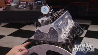
(Pat)>> The cam shaft is degreed and comes in at 106 degrees of intake centerline, which is eight degrees advanced. Perfect for our street engine. While the degree wheel is still on, we'll mockup the cylinder head with checking springs in the number one position. We do this to check piston to valve clearance. [ Music ] The adjustable guide plates and seven-sixteenths rocker studs are installed along with the hydraulic roller lifters. Then an adjustable push rod is put into place to check valve train geometry and for push rod length. We'll mark the valve tip to help see where the rocker arm tip rides through its cycle. We're using Comp's 1.7 ratio Ultra Pro Magnum steel body rocker. Once it's set up, we'll use a steel plate to hold our magnetic base dial indicator. The valvetrain geometry is checked by opening the valve to half lift and looking at the relationship of the pivot point, rocker tip, and valve stem. This should create a 90-degree angle between the valve stem and the center line of the tip to fulcrum. The point where the valve is closest to the piston occurs within a range depending on the cam shaft profile. Typically, that is eight to 14 degrees after t-d-c during split overlap on the intake and the same range on the exhaust between eight and 14 degrees before t-d-c on split overlap. We'll check within this range to find the closest clearance for both valves. Our minimum clearance on the intake side is 178 thousandths and 245 thousandths on the exhaust. Now we can check the amount of sweep on the top of the valve, which measures in at 65 thousandths, outstanding! With the geometry looking great we can measure the adjustable push rod to determine the correct push rod length. Ours will be seven inch 850 thousandths. [ drill humming ]
(Pat)>> Since we are not moving the cam, we'll apply some thread locker and torque the cam bolt to 45 pound feet. [ Music ] This one has those silky smooth rings.
(Frankie)>> Tiny, tiny, low tension rings. Like pushing it in with a pinkie.
(Pat)>> The piston and rod assemblies are installed in our squeaky clean bores. The connecting rods are Eagle Specialty Products H-beams with a 6-250 center to center length and a 928 bush small end for floating wrist pins. They are secured with ARP 2,000 rod bolts. Final torque to achieve our proper bolt stretch is 90-pound feet.
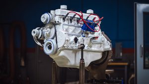
(Frankie)>> Sometimes people can get upset with our unconventional paint choices but given this engine's Ford blue finish the only thing getting triggered today is the ignition system.
(Frankie)>> A great engine deserves a great paint job. After prepping the Windsor block with lacquer thinner we'll mask off the bores, the valley, and the area around the timing cover as well as any open ports. [ Music ] For a quality paint job we're using this engine enamel that we got from Summit Racing Equipment. The color is Ford blue. This paint can be brushed on, but for our application we're gonna thin it out a bit so we can use a spray gun. [ Music ] After prepping the block with primer we'll do a light coat to ensure good coverage and finish it out with a few heavier coats to give it that rich, glossy look. [ paint gun hissing ]
(Pat)>> Next we'll apply a thin bead of silicone on the block. After that the timing cover gasket is gently laid into place. Finally, we'll add another thin bead of silicone for extra insurance. The timing cover is snugged down with ARP stainless steel fasteners, and then tightened evenly. [ ratchet clicking ]
(Pat)>> An ATI damper with a 10 o'clock timing pointer position is pressed on. [ Music ] Then our Holley e-f-i 36-minus-1 crank trigger wheel is bolted on. For a modern e-f-i setup like we're using this will give the ultimate in crankshaft position accuracy. It's torqued to 45-pound feet. [ Music ] Our small block Ford crank trigger kit comes with a hall effect pick up and bracket that bolts up to the timing cover. We also customized an MSD timing pointer so that we can precise verify the number one piston's position. [ Music ] We'll set true t-d-c on the number one cylinder using a piston stop. Then adjust the pointer accordingly. [ Music ] [ ratchet clicking ] [ Music ]
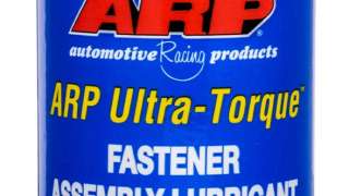
(Pat)>> Next we can turn the engine up to t-d-c on number one cylinder, align the crankshaft sensor with the marked tooth, and set the air gap between the two at 40 thousandths. [ Music ] We have a bunch of great parts going on our stroker Windsor, but they don't mean a whole lot if you can't hold them together, and for that we always go with a quality fastener from ARP. We are gonna be bolting our cylinder heads on momentarily. So, we ordered up one of their head bolt kits. These have an 87-40 chro-moly fastener. It has 180,000 p-s-i of tensile strength. Now these are not an o-e-m fastener. So, they don't take an o-e-m spec. The great thing about ARP is they include with their kits parallel ground washers, their ARP Ultra Torque assembly lube, and most importantly a detailed set of instructions. Because these aren't an o-e-m fastener they don't take an o-e-m torque spec. So, you can't just look one up online and just find a torque spec for an o-e-m application. The instructions tell you exactly how to torque the head so you get the maximum benefit. Because our Ford only has 10 head bolts per side, we need that maximum clamp load to seal the cylinder pressures we're gonna make. So, we're gonna lube them up and stick them in.
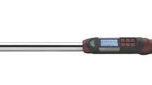
(Frankie)>> ARP Ultra Torque assembly lube goes under the head of the bolt. Next the washers slide on, and the threads receive Ultra Torque as well. Our ARP head bolts are gonna be holding on a set of AFR Renegade 220-cylinder heads that we got from Summit Racing Equipment. These are gonna work great on our 410 stroker cause they have a 220cc competition c-n-c ported intake port that flows up to 331 c-f-m. It all goes through a 2-100 intake valve into a 58cc c-n-c combustion chamber and goes out through a 1-570 exhaust valve. Both valves have eight millimeter stems, and for valvetrain control we have a 1-550 o-d dual spring. That's gonna have 155 pounds on the seat, and 475 pounds at open. We're gonna put the rocker studs and guide plates on once we get our push rods, but for now we'll get the cylinder heads bolted on and seal up our cylinders. The head gaskets are Cometic MLS with a 4-100 bore and a 40 thousandths compressed thickness, which gives us a measured compression ratio of 10.36 to 1. User friendly for pump gas. The heads are torqued in three steps to a value of 100-pound feet. The Matco digital half inch torque wrenches make it so convenient because we can pre-program all three torque values and switch between them at the push of a button. [ Music ]
(Pat)>> Alright!
(Frankie)>> Finally starting to actually look like an engine. The best part, right?
(Pat)>> We even painted it a conventional Ford color.
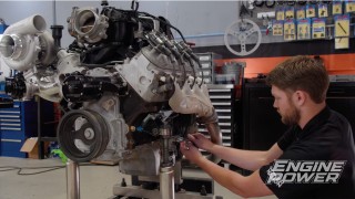
(Frankie)>> We have a good, solid bottom end, forged rotating assembly, nice, beautiful cylinder heads. This is gonna be a nice engine when it's done, and it already looks nice.
(Pat)>> More importantly than looking nice is running nice, and I think it's gonna run spectacular. I'm very excited about that.
(Frankie)>> For more information or to see more cool stuff like this check out our website.
Show Full Transcript
(Pat)>> Today on Engine Power we're building a winning Windsor, and the best part about it is, well you'll just have to watch to find out. [ Music ]
(Pat)>> Hi everyone, and welcome to Engine Power. We are very excited to start a brand new project for you. We've done a few Chevys and even a small block Mopar, but today it is all about Ford power. These are the makings of a 410 cubic inch stroker small block Windsor. This is gonna be a heavy hitter on pump gas, but what makes all this extra special is we have partnered up with Holley so you can enter to win this exact engine for yourself.
(Frankie)>> And that's really exciting for one of you because this engine is gonna come with a bunch of great parts, including a fully forged rotating assembly with Eagle crank and rods and a Mahle piston, a set of AFR 220 competition ported cylinder heads, a Holley hi-ram intake manifold with their 105 millimeter throttle body intake top, and the whole engine will be controlled with Holley e-f-i, including their Terminator-X Max and their Smart Coil Kit. But before we can get all of this in there and get it in one of your driveways we have a lot of work to do, including some block prep.
(Pat)>> A bunch of that!
(Frankie)>> Let's get started. [ Music ] First up is removing the threaded oil gallery plugs throughout the block. This will allow us to drive out the pressed in plugs in the front of the engine. We'll do this with a long piece of threaded rod and a hammer. To remove the plug from the lifter gallery crossover port we'll drill a pilot hole, run in a self tapping screw, and use a slide hammer to pop it out. [ Music ] Next, we'll port the oil inlet from the pump using the gasket as a template. A series of carbide burrs and a light touch gets the job done safely. [ Music ] It's important to go slowly and check your work. We say it often but it bears repeating. It's easier to remove more material but very hard to put it back. Throughout the process we'll continue to use the gasket as a guide. [ air tool humming ]
(Frankie)>> To further smooth out the finish a cartridge roll comes next. [ air tool buzzing ]
(Frankie)>> Once we're happy with the surface we'll follow the oil's path, smoothing as we go. [ air tool buzzing ] [ Music ]
(Frankie)>> It's important to have a wide variety of carbide shapes and sizes to get into all the block's nooks and crannies.
(Pat)>> Moving on, we'll tune up the drain backs in the lifter valley. Notice that the burr is running at moderate speed. This helps maintain control and not move too fast. We'll give the same treatment to the pressurized oil crossover for the lifters. [ Music ] We are tapping the oil galleries that had press in plugs in favor of threaded pipe plugs. This serves a couple of different purposes. First the plug cannot pop out under pressure unlike a pressed in one. Second, it makes the oil galleries easily serviceable since we can readily remove and reuse the plug. The holes are tapped so the plug is just under flush from the surface because if you go too deep you can potentially block off another oil gallery. [ Music ] Once we're happy with the fit we'll chamfer the outside. Every bolt hole is finished with a light chamfer. [ drill humming ]
(Frankie)>> There are several reasons to deburr a block, which we'll get to in a minute, but the one that is my favorite is that it stops the paper shop towels from tearing when you're wiping off the engine. [ Music ]
(Pat)>> Oh yeah, very nice hustle on this one.
(Frankie)>> It wasn't too bad. A couple of hours into it, but the great part is that this block is definitely gonna benefit from this.
(Pat)>> I would agree with that. Now this seems like a tedious task, but this can benefit any engine that you work on. I don't care what it is. Smooth oil flow is always a great thing and working with a block that you can cut yourself, and deburring it eliminates places for stress risers to start. So, whoever gets this one's gonna get a nice piece. What's next?
(Frankie)>> We've got to clean it. I'm pretty much done here. It's all deburred. The oil returns are all smoothed out. All the pressure ports are all smooth out. So, I've got to get this in the cleaner, get the bores clean, get all the oil galleries clean, and then we can move on to assembly.
(Pat)>> To the cleaner! Bring it with you!
(Frankie)>> It's oil galleries, not galley. A galley's a kitchen on a ship.
(Pat)>> Yeah! [ Music ] Our jet washer runs at 150 degrees. So, we'll use it to wash the block for about 30 to 40 minutes. [ Music ]
(Frankie)>> Up next, they may be small but piston rings can have a big impact on your engine's performance.
(Pat)>> With Frankie's enthusiastic and strangely cheerful help assembly of the 410-inch Windsor begins. To ensure that the cap is aligned and the bolts won't bind up in the bolt holes we start by gently running down the fasteners, and then we cap the main with a dead blow hammer to seat it. Now the bolts can be snugged down and torqued to a final value of 100-pound feet. The crankshaft journal is precisely measured with a micrometer, and that measurement is transferred to our Sunnen dial bore gauge. [ Music ] With the bearings installed the housing bore is measured to determine its vertical oil clearance. Number five main measures right at three thousandths, which is technically one ten-thousandths above the stock spec, but for our high performance engine it will work great. [ torque wrench clicking ]
(Pat)>> As always, we do this for every housing bore. [ Music ] The same process is done for each individual connecting rod. We'll measure the journal, transfer the measurement to the dial bore gauge, and check the rod. They all came in between 22 and 24 ten-thousandths, excellent! [ grinder buzzing ]
(Pat)>> Accuracy of the ring gap is important, and it depends on what the engine is used for. As an engine builder you determine what ring gap fits your needs. Since this is a high performance engine that will definitely see some abuse, the ring gaps are opened up to 24 thousandths on the top ring and 26 thousandths on the second ring. [ grinder buzzing ]
(Pat)>> We always gap the second compression ring first. For one, the second ring is usually gapped a little bigger. Plus, this gives you the time to dial everything in perfectly for that ultra critical top ring gap. After gapping 16 rings you'll be glad it's over, but you'll be even happier that the job is done to your liking. The right tools, like this Summit Racing ring squaring tool, helps you be consistent and accurate. [ Music ] Putting piston assemblies together is not hard, but it can be a bit challenging to install the lock. Fortunately, these locks are a solid piece of round wire instead of a spiral lock. So, they go in a bit easier. The pistons are a Mahle Power Pack Kit forged from 26-18 alloy. They have a one millimeter, one millimeter, two millimeter ring pack, 927 thousandths heavy duty wrist pins, a 20cc effective dish volume, and they are phosphate coated with a graphal anti-friction coating on the skirts. We are almost ready to start assembling our stroker Windsor, but before we do that I'd like to stop and take a little bit of time to talk about something that's very important for engine operation, and that is piston ring tension. Why, because the ring tension is a big player in friction in the engine, and the more friction we can reduce, still control oil and seal combustion, the more power our engine will make, and I have a few examples here from Summit Racing Equipment that will explain everything. Because of improvements in the material quality and machining techniques the ring pack has gotten smaller and smaller over the years and still done a great job in sealing things up. Back in the day a common size ring pack was a 564ths top and second ring with a three-sixteenths oil ring. Now the oil ring was the main contributor to tension. A normal oil ring has about 20 to 25 pounds of tension when you pull it on a scale. An improvement to that size was to reduce the top and second compression rings to a sixteenth width. That helped with some of the friction, but it still had that three-sixteenths ring pack. You can reduce the pull on that ring pack by getting a lower tension oil ring. They're used in racing, but a better way of doing it is reduce the total size of all of the ring pack. Our piston has a one millimeter, one millimeter, two millimeter ring pack, which not only reduces the friction, it also improves sealing because of the quality of the components. This stock ring setup pulls at about 22 pounds and is very notchy. Our vastly improved aftermarket setup pulls at about 10 pounds, slick! It can be a little daunting picking what ring pack will work for your application, but if you contact the experts at Summit Racing's tech department they can steer you in the right direction. Up next, our math teachers always said geometry was important, and they were right.
(Pat)>> With all clearances set and everything tuned in we're ready for final assembly. The main bearings get a coat of high viscosity assembly lube. Windsors have a one piece rear main seal, and this one is Teflon based. So, it goes on the crankshaft dry. It came with a plastic sleeve to make installation easier. The foundation for our stroker is a 43-40 forged crankshaft from Eagle Specialty Products. It has a four-inch stroke and a 125 thousandths radius on the journals for added strength. It was internally balanced at our favorite local machine shop, Shacklett Automotive Machine. The ARP main bolts are final torqued to 100 pound feet. Thrust is set by wedging the crank forward and tightening the center main cap. [ Music ] Crankshaft end play measures at three thousandths. The hydraulic roller cam is made by Comp. Duration at 50 thousandths lift is 248 degrees on the intake and 258 degrees on the exhaust. Lobe separation angle is 114 degrees. Lift at the valve with all rocker arms is 646 thousandths on both the intake and exhaust. The cam shaft thrust plate gets torqued down to 14 pound feet. The camshaft dowel slides in, and the threaded oil gallery plugs are tightened down. Assembly lube goes on the plate, and then Comp's billet double roller timing set comes next. [ tapping ] [ drill humming ]
(Pat)>> The cam shaft is degreed and comes in at 106 degrees of intake centerline, which is eight degrees advanced. Perfect for our street engine. While the degree wheel is still on, we'll mockup the cylinder head with checking springs in the number one position. We do this to check piston to valve clearance. [ Music ] The adjustable guide plates and seven-sixteenths rocker studs are installed along with the hydraulic roller lifters. Then an adjustable push rod is put into place to check valve train geometry and for push rod length. We'll mark the valve tip to help see where the rocker arm tip rides through its cycle. We're using Comp's 1.7 ratio Ultra Pro Magnum steel body rocker. Once it's set up, we'll use a steel plate to hold our magnetic base dial indicator. The valvetrain geometry is checked by opening the valve to half lift and looking at the relationship of the pivot point, rocker tip, and valve stem. This should create a 90-degree angle between the valve stem and the center line of the tip to fulcrum. The point where the valve is closest to the piston occurs within a range depending on the cam shaft profile. Typically, that is eight to 14 degrees after t-d-c during split overlap on the intake and the same range on the exhaust between eight and 14 degrees before t-d-c on split overlap. We'll check within this range to find the closest clearance for both valves. Our minimum clearance on the intake side is 178 thousandths and 245 thousandths on the exhaust. Now we can check the amount of sweep on the top of the valve, which measures in at 65 thousandths, outstanding! With the geometry looking great we can measure the adjustable push rod to determine the correct push rod length. Ours will be seven inch 850 thousandths. [ drill humming ]
(Pat)>> Since we are not moving the cam, we'll apply some thread locker and torque the cam bolt to 45 pound feet. [ Music ] This one has those silky smooth rings.
(Frankie)>> Tiny, tiny, low tension rings. Like pushing it in with a pinkie.
(Pat)>> The piston and rod assemblies are installed in our squeaky clean bores. The connecting rods are Eagle Specialty Products H-beams with a 6-250 center to center length and a 928 bush small end for floating wrist pins. They are secured with ARP 2,000 rod bolts. Final torque to achieve our proper bolt stretch is 90-pound feet.
(Frankie)>> Sometimes people can get upset with our unconventional paint choices but given this engine's Ford blue finish the only thing getting triggered today is the ignition system.
(Frankie)>> A great engine deserves a great paint job. After prepping the Windsor block with lacquer thinner we'll mask off the bores, the valley, and the area around the timing cover as well as any open ports. [ Music ] For a quality paint job we're using this engine enamel that we got from Summit Racing Equipment. The color is Ford blue. This paint can be brushed on, but for our application we're gonna thin it out a bit so we can use a spray gun. [ Music ] After prepping the block with primer we'll do a light coat to ensure good coverage and finish it out with a few heavier coats to give it that rich, glossy look. [ paint gun hissing ]
(Pat)>> Next we'll apply a thin bead of silicone on the block. After that the timing cover gasket is gently laid into place. Finally, we'll add another thin bead of silicone for extra insurance. The timing cover is snugged down with ARP stainless steel fasteners, and then tightened evenly. [ ratchet clicking ]
(Pat)>> An ATI damper with a 10 o'clock timing pointer position is pressed on. [ Music ] Then our Holley e-f-i 36-minus-1 crank trigger wheel is bolted on. For a modern e-f-i setup like we're using this will give the ultimate in crankshaft position accuracy. It's torqued to 45-pound feet. [ Music ] Our small block Ford crank trigger kit comes with a hall effect pick up and bracket that bolts up to the timing cover. We also customized an MSD timing pointer so that we can precise verify the number one piston's position. [ Music ] We'll set true t-d-c on the number one cylinder using a piston stop. Then adjust the pointer accordingly. [ Music ] [ ratchet clicking ] [ Music ]
(Pat)>> Next we can turn the engine up to t-d-c on number one cylinder, align the crankshaft sensor with the marked tooth, and set the air gap between the two at 40 thousandths. [ Music ] We have a bunch of great parts going on our stroker Windsor, but they don't mean a whole lot if you can't hold them together, and for that we always go with a quality fastener from ARP. We are gonna be bolting our cylinder heads on momentarily. So, we ordered up one of their head bolt kits. These have an 87-40 chro-moly fastener. It has 180,000 p-s-i of tensile strength. Now these are not an o-e-m fastener. So, they don't take an o-e-m spec. The great thing about ARP is they include with their kits parallel ground washers, their ARP Ultra Torque assembly lube, and most importantly a detailed set of instructions. Because these aren't an o-e-m fastener they don't take an o-e-m torque spec. So, you can't just look one up online and just find a torque spec for an o-e-m application. The instructions tell you exactly how to torque the head so you get the maximum benefit. Because our Ford only has 10 head bolts per side, we need that maximum clamp load to seal the cylinder pressures we're gonna make. So, we're gonna lube them up and stick them in.
(Frankie)>> ARP Ultra Torque assembly lube goes under the head of the bolt. Next the washers slide on, and the threads receive Ultra Torque as well. Our ARP head bolts are gonna be holding on a set of AFR Renegade 220-cylinder heads that we got from Summit Racing Equipment. These are gonna work great on our 410 stroker cause they have a 220cc competition c-n-c ported intake port that flows up to 331 c-f-m. It all goes through a 2-100 intake valve into a 58cc c-n-c combustion chamber and goes out through a 1-570 exhaust valve. Both valves have eight millimeter stems, and for valvetrain control we have a 1-550 o-d dual spring. That's gonna have 155 pounds on the seat, and 475 pounds at open. We're gonna put the rocker studs and guide plates on once we get our push rods, but for now we'll get the cylinder heads bolted on and seal up our cylinders. The head gaskets are Cometic MLS with a 4-100 bore and a 40 thousandths compressed thickness, which gives us a measured compression ratio of 10.36 to 1. User friendly for pump gas. The heads are torqued in three steps to a value of 100-pound feet. The Matco digital half inch torque wrenches make it so convenient because we can pre-program all three torque values and switch between them at the push of a button. [ Music ]
(Pat)>> Alright!
(Frankie)>> Finally starting to actually look like an engine. The best part, right?
(Pat)>> We even painted it a conventional Ford color.
(Frankie)>> We have a good, solid bottom end, forged rotating assembly, nice, beautiful cylinder heads. This is gonna be a nice engine when it's done, and it already looks nice.
(Pat)>> More importantly than looking nice is running nice, and I think it's gonna run spectacular. I'm very excited about that.
(Frankie)>> For more information or to see more cool stuff like this check out our website.
