Engine Power Featured Projects
Engine Power Builds
Want more content like this?
Join the PowerNation Email NewsletterParts Used In This Episode
ARP
ARP Bolts & Fasteners
ARP
ARP Header Studs
The Industrial Depot
Tools, Hardware, Shop Supplies
Episode Transcript
(Pat)>> You're watching Powernation!
(Frankie)>> After making some careful calculations and bolting down some hand ported cylinder heads...
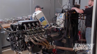
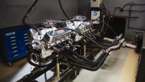
(Pat)>> ...our 4.3-liter V-6 hits the dyno! Yes! [ MUSIC ]
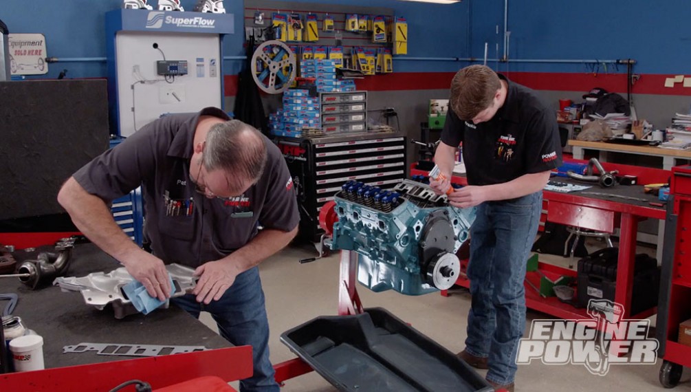
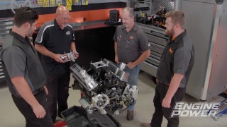
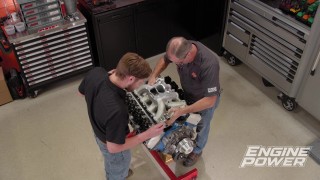
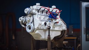
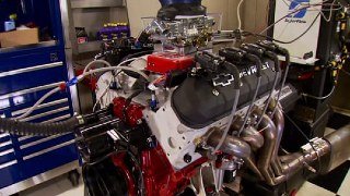
(Pat)>> Hey everyone, welcome to Engine Power. Today we are gonna be continuing on a very fun project that we are doing quite frankly because we have gotten a lot of requests from you viewers to work on one. So, we've dragged one out of the warehouse and started a build. This particular engine is relatively easy to work on because it shares some common architecture and parts with something us gearheads should be very familiar with, the gen one small block Chevy V-8. This is its little brother, a 4.3-liter V-6. This has powered a bunch of vehicles over the years, but it is still very common in the hot rod community to work on. Ours has had a ton of work done already but it still requires more work to get it running. If you are not familiar with this project and want to see how the engine has gotten to this stage have a look at this.
(Frankie)>> We reused the stock crankshaft and rods but upgraded the pistons to a lightweight forged set from Wiseco. They also have a flat top design with 7cc valve reliefs to help improve compression. To accommodate the new pistons the crankshaft was balanced, and the rods were weight matched.
(Pat)>> We wanted to upgrade the camshaft, but we weren't going to get crazy on the specs. So, we spec'ed out a Comp hydraulic roller. We bolted up a timing set, and the installed the number one piston to degree the cam. The cam's intake center line came in at 106 degrees, which is 8 degrees advanced. Finally, the rest of the rotating assembly was installed.
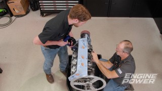
(Frankie)>> Now that you're all caught up we can go ahead and finish up our three quarter 350. This means getting the oiling system installed, adding the timing cover and oil pan, and most importantly our hand ported cylinder heads and induction package. Some of these parts are a little bit harder to get depending on your year and if you didn't start with them in the first place. Since we started with a remanufactured long block, we had some great help sourcing parts, and I think we have everything we need to get it running. Normally during the assembly process, we kind of push through and try and get the engine on the dyno and see what it'll do. That's because it's everybody's favorite part, but on this one we're gonna take it a little bit slower, take our time, and show you some important tech along the way. We'll go ahead and add a little bit of assembly lube to our front cover seal since it's rubber. If you have a Teflon seal you don't want to add any oil or lubrication to it because Teflon has its own lubricity and adding any more could potentially make it leak. So we'll put a little bit right on the seal face, and then we can get it installed.
(Pat)>> In preparation for initial startup it's always a good idea to lubricate the timing assembly with engine oil. [ drill buzzing ]
(Pat)>> The rear main seal is Teflon. So it does not get lubricated. A thin layer of silicone is laid on both sides of the gasket. [ MUSIC ] [ ratchet clicking ]
(Pat)>> The next thing we're going to install is the oil pump and oil pan. You can put the pump on with either a bolt or a stud. We're choosing to use an ARP stud. The important thing with that is it has to be the correct length. The through hole that goes into the cap goes all the way down to the main bearing. If you put something in that's too long you can actually apply pressure to the bearing itself when it's tightened, and that is definitely a bad thing. So, we've already measured that up and we have the right studs. We're gonna put a little thread locker on it and install it in the block.
(Frankie)>> Another really important factor to putting on the oil pan and the pickup is measuring the clearance between the pickup and the bottom of the pan itself. Now there's a couple of different ways to do this but the best way is to physically measure it. So, we've already taken a straight edge, and put it across our pan, and measured to the bottom, and it's about seven and an eighth. A huge factor in that is the thickness of the gasket. So, we'll add another eighth inch for that, and that brings it to about seven and a quarter. So, on our pickup we're looking for about seven inches, or just under, and that will give us the proper clearance. The way we'll do that is install the pump, set the straight edge across it, measure both sides to the oil pan rails and average them. Then once we have everything set an important step on these pumps, because the pick-up is only pressed in and not held in with a bolt, is to actually tack weld it into place. They are a press fit but under normal operation like vibration and high engine loads, they can kinda vibrate loose and start moving around, and we definitely don't want that. So, we'll just tack it into place for extra insurance. First, we'll mock the pump up on the engine, lay a straight edge onto the pick-up, and take careful measurements down to the oil pan rail on either side. [ MUSIC ] With everything looking good it's time to tack the pick-up into place.
(Pat)>> This is just a small tack and not a full weld. A minimal amount of heat is used to tack it. Too much heat can weaken the relief spring and potentially cause warpage. The pump is left fully assembled. So, it has more area to dissipate heat.
(Frankie)>> The pump is pre-lubed with some oil to protect the gears, and the heavy-duty oil pump driveshaft slides into position. [ MUSIC ] The nut is torqued to 55-pound feet. [ MUSIC ] We'll apply some r-t-v to the parting lines and mating surfaces, and the one-piece oil pan gasket drops on. [ MUSIC ] A little more r-t-v on the corners and the oil pan is bolted down with some ARP bolts and a black oxide finish. [ MUSIC ]
(Pat)>> Up next, the more you know about any engine the better you can make it run. We'll show you how to calculate compression ratio.
(Frankie)>> The 4.3-liter V-6 Chevy build continues with a harmonic balancer. Please use an installation tool not a hammer and a piece of wood. It's worth doing it the right way so you don't accidentally damage the balancer. [ drill humming ]
(Frankie)>> The degree wheel, a piston stop, and a magnetic base pointer are all used to check true t-d-c. The engine is turned each way and the piston is run up to the stop. The degree wheel reading should be the same when the piston touches the stop. In our case it is 18 degrees before and after top dead center. Knowing this, when we set the degree wheel to zero we know we're at true t-d-c. We'll scribe a new mark on the timing cover to indicate where true t-d-c actually is.
(Pat)>> In the spirit of slowing down and showing you more tech we're gonna do something for you that we haven't done in a while. We're gonna measure some volumes on the engine to calculate an accurate static compression ratio, and that involves the top of the piston and the cylinder head's combustion chamber. Normally you can get data on the top of your piston from the piston manufacturer, whether it's a dish or a dome, to what c-c it is, and you can also research and find out what your combustion chamber volume is on your cylinder head somewhere on the internet, but because those are both unknown's to us we are going to calculate those volumes ourselves.
(Frankie)>> The way we're gonna do the top of the piston is pretty simple and just takes a little bit of math. What we're gonna do is roll the piston down into the bore, apply some assembly grease around the edges, and then roll it back up to a measured value. Then we can set our plexiglass plate on and physically pour it for a volume. [ MUSIC ]
(Pat)>> A minimal amount of grease is used to stop the fluid from leaking into the crankcase, which would cause an inaccurate measurement. Now we'll run our piston up to a precise 50 thousandths below the deck surface. Excess grease in the cylinder is removed because it will take up some volume. [ MUSIC ] A critical operation is to make sure the burette has a precise amount of isopropyl alcohol. We'll purge the air from the fill side of the burette to get a more accurate reading. Then it is refilled to zero. [ MUSIC ] Sometimes it's easier to have an extra pair of hands to hold the burette in place. We carefully fill the cylinder to the top, paying attention not to spill anything outside the plate. [ MUSIC ] Now we'll get the ready from the burette.
(Frankie)>> So since we put our piston 50 thousandths in the hole we've already gone ahead and calculated how much volume that space should take up. So, we've gone ahead and calculated the volume of the cylinder and then multiplied it by 16.39 to convert it into cubic centimeters, and we had a measured volume, measured total volume, of 19.4. So, we can go ahead and subtract our 10.45 from that and we'll get 8.95cc, which is our actual piston top volume. And remember this is a measured volume, so it takes into account around the top ring land as well.
(Pat)>> We're going to measure the combustion chamber volume the same way we did the piston, although now there's no math involved. All we have to have are the valves in, obviously the spark plug, get it up on a stand, put the plate on, and give it a pour. We've already reset our graduated cylinder back to 100cc. So it's strictly a physical measurement. After applying a thin layer of grease to the valve seat we'll install the valves, some checking springs, and the spark plug. We'll tilt the head up slightly to keep air bubbles from forming in the chamber during the fill. Using the same process as before we'll determine the volume of the chamber. It measures 61.4cc.
(Frankie)>> Now that we have our values we can go ahead and calculate our compression ratio. To do this we need to know five different volumes, all in cubic centimeters. The first is the swept volume, or displacement of one cylinder, which is 727.54cc. Volume two is the top of the piston, which we measured at 8.95cc. Volume three is the deck clearance, or volume of space between the deck surface and the top of the piston, which we calculated to be 4.59cc. Volume four is our head gasket, which is 8.49cc, and finally volume five is our combustion chamber, which Pat measured at 61.4cc. for our calculation we'll add up all five values to get a total volume of 810.97cc, and then divide it by the total volume minus the swept volume. This gives an accurate compression ratio of 9.72 to one.
(Pat)>> Measuring and calculating the compression ratio is just like degreeing the cam for us. Even though we don't show it to you every time we do it every time. With our old setup in this engine, with the dish piston and how far the piston was down in the hole, we had a calculated compression ratio of 8.65 to one. With our new piston at 9.72 to one that will definitely help us in the horsepower department.
(Pat)>> Up next, the V-6 gets heavy duty springs, roller rockers, and a carbureted intake.
(Frankie)>> Then it's off to the dyno cell.
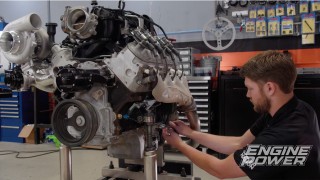
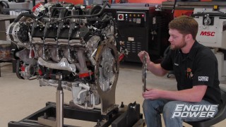
(Pat)>> Our 4.3 liter is going together rather well, but we still have a few things to do. Next, we are going to stick the valvetrain and induction on it to get it ready for the dyno, and that will start by getting our lifter assemblies in. From the factory this is a hydraulic roller setup. So, it came with all new parts, and we are going to reuse them for our application because they're gonna work great. It starts with a hydraulic roller lifter and a tray. Now if this looks familiar this is the same type of setup that is used to retain the lifters in an LS. There is no tie bar on the lifters. It has been aligned and retained by a tray. After that we're gonna get our cylinder heads installed. Now if you remember, previously we have done some work to these heads, and shown how you can do some porting at home and improve flow but not get yourself into any trouble by removing too much material and causing a bad situation. To support our new cam, we've also added a new valve spring assembly. It is from Comp, and it is a spring retainer and keeper assembly. We had to setup individual spring heights to get our installed height correct for the seat and open pressures we wanted, and we've done that with a height mic. Our new installed height on our spring is one inch, 740 thousandths, and that will give us 126 pounds of seat pressure and 360 pounds of open pressure. That is great for what we're gonna be doing and will even support more if we give it some more juice. The valve stems are coated with engine assembly grease and slid into the guides. [ MUSIC ] The new valve stem seals are installed, followed by the valve spring shims, the springs, and retainers. New valve locks will keep them in place.
(Frankie)>> The lifters are oiled, slid into place, and the trays are torqued to 25-pound feet. We are using ARP head studs, and since the fasteners go into the water jacket thread sealant is required on all of them. Cometic m-l-s head gaskets with a 4.060 bore and 40 thousandths compressed thickness will seal up the heads. [ MUSIC ] The head studs are run down by hand. Then lubed and torqued to 80-pound feet. Now that our cylinder heads are clamped down on our engine we can move on and install the rest of our valvetrain. That's gonna mean new rocker studs, new rockers, and push rods. The stock rockers are stamped steel design and the stock rocker studs are non-adjustable, and that works in the stock application but its just not gonna cut it for what we're doing. So, we're gonna upgrade them. We're going with a set of ARP 87-40 rocker studs that are fully adjustable, and that will allow us to run some full roller rockers that we got from Summit Racing. They're scorpion 1.6 ratio roller rockers, and they have a self-aligning tip that will allow us to not run guide plates because they're a little bit tricky to make fit on these cylinder heads. We went with a 1.6 ratio so we could get a little more lift at the valve. We also went ahead and measured for a new push rod length since we've been changing these components, and we have some seven inch, five-sixteenths, 80 wall push rods from Comp. We're gonna start by applying some sealer to the threads of the rocker studs since all the rocker stud holes are through holes. So they go into either the coolant passages or the intake ports. Then we'll get them torqued down and get all of our other components put on. Following ARP's instructions they are torqued to 50-pound feet. Extreme pressure lube is applied to the push rod ends, and they are dropped in. The same lube is applied to the valve tips, the other end of the push rods, and the rocker stud threads. The hydraulic rollers are set to zero lash, plus one half turn of pre-load in the firing order of the engine, 1-6-5-4-3-2. [ MUSIC ]
(Pat)>> We're not known for painting engines in conventional colors. So this time we're using Chrysler green. [ spray gun hissing ]
(Pat)>> The valve covers receive a coat of wrinkle black and some stripes also in Chrysler green. As always, we glue the gaskets down with weatherstrip adhesive. The mating surfaces of the block and the heads receive silicone as well as the China walls. Before all of the fasteners are tightened, we make sure that the intake ports are lined up properly on the Edelbrock Performer intake manifold. Finally, our fancied up valve covers are tightened down with ARP fasteners.
(Frankie)>> Up next, you don't need eight cylinders to have a lot of fun.
(Pat)>> Alright, what carburetor is on that right now?
(Frankie)>> I put that QFT 450 on it. If you do the math around 5,500 this thing needs like 423 c-f-m. So, I went with the 450.
(Pat)>> Okay I'll buy that. As far as pulls I am going to do something that I normally don't do. We're gonna start this at like 1,500, and let's run it up to 4,500. [ engine idling ]
(Pat)>> Right to it, look at that!
(Frankie)>> Wide open at 1,500!
(Pat)>> O-2's look good!
(Frankie)>> Oil pressure's great, look at that! [ engine revving ]
(Frankie)>> Wow!
(Pat)>> 289.3-pound feet of torque, 244.9 for horsepower.
(Frankie)>> After 2,400 over 280 the entire time.
(Pat)>> We're not gonna change anything. Let's just pull it higher.
(Frankie)>> See where it peaks. [ engine revving ]
(Pat)>> I think it broke 250!
(Frankie)>> It was holding pretty good though.
(Pat)>> Yes, 253! It peaks at 5,100.
(Frankie)>> That's pretty close to what we were guessing.
(Pat)>> 288.1.
(Frankie)>> Heck yeah!
(Pat)>> The first change that we're gonna make is the spacer. We're replacing the one-inch piece with a two inch design. This may not make a big difference on this lower horsepower V-6 but there's only one way to find out. [ engine revving ]
(Pat)>> 254, 288.
(Frankie)>> It looks pretty close.
(Pat)>> It's almost number for number. They're literally identical past 4,400. What do we have for carburetors?
(Frankie)>> We have a bunch of different options, but we have this really nice 750 that's kinda like old reliable. I think that'd be a good ticket on this one.
(Pat)>> We have that old school annular booster one. So let's give that a try!
(Frankie)>> Yeah, stick it on there, see what it does. [ engine revving ]
(Pat)>> Okay 259.9, I'll call that 260, and 289.9 for torque. So that's a nice little jump.
(Frankie)>> It just kinda smoothed out and kinda picked up above 4,500-ish. That's pretty nice! Since the 750 made a good improvement, we decided to go big with our 950 c-f-m QFT Black Diamond. [ engine revving ]
(Frankie)>> Dang, oh yeah.
(Pat)>> 296-pound feet of torque, and 262 horsepower. What did that make over the 450?
(Frankie)>> There's a little bit where they kinda match but then they separate back out.
(Pat)>> It makes more power at 2,100, there you go!
(Frankie)>> That's pretty cool.
(Pat)>> For what it is at 266 inches we almost made 1 horse per cube, but we made really decent torque. For something that originated at 150, 160 horse we are spectacular. Just because it's a six cylinder and it may be warmed over street engine, that doesn't mean that you don't spend the same amount of time on it. I don't care if it's a forklift engine or an NHRA Pro Stocker you put the same amount of work into everything that you can put your hands on making it as good as you can with the resources that you have and the parts that you have. Great success!
(Frankie)>> Another good day.
(Pat)>> To find out more about anything that you've seen today visit Powernation TV dot com.
Show Full Transcript
(Frankie)>> After making some careful calculations and bolting down some hand ported cylinder heads...
(Pat)>> ...our 4.3-liter V-6 hits the dyno! Yes! [ MUSIC ]
(Pat)>> Hey everyone, welcome to Engine Power. Today we are gonna be continuing on a very fun project that we are doing quite frankly because we have gotten a lot of requests from you viewers to work on one. So, we've dragged one out of the warehouse and started a build. This particular engine is relatively easy to work on because it shares some common architecture and parts with something us gearheads should be very familiar with, the gen one small block Chevy V-8. This is its little brother, a 4.3-liter V-6. This has powered a bunch of vehicles over the years, but it is still very common in the hot rod community to work on. Ours has had a ton of work done already but it still requires more work to get it running. If you are not familiar with this project and want to see how the engine has gotten to this stage have a look at this.
(Frankie)>> We reused the stock crankshaft and rods but upgraded the pistons to a lightweight forged set from Wiseco. They also have a flat top design with 7cc valve reliefs to help improve compression. To accommodate the new pistons the crankshaft was balanced, and the rods were weight matched.
(Pat)>> We wanted to upgrade the camshaft, but we weren't going to get crazy on the specs. So, we spec'ed out a Comp hydraulic roller. We bolted up a timing set, and the installed the number one piston to degree the cam. The cam's intake center line came in at 106 degrees, which is 8 degrees advanced. Finally, the rest of the rotating assembly was installed.
(Frankie)>> Now that you're all caught up we can go ahead and finish up our three quarter 350. This means getting the oiling system installed, adding the timing cover and oil pan, and most importantly our hand ported cylinder heads and induction package. Some of these parts are a little bit harder to get depending on your year and if you didn't start with them in the first place. Since we started with a remanufactured long block, we had some great help sourcing parts, and I think we have everything we need to get it running. Normally during the assembly process, we kind of push through and try and get the engine on the dyno and see what it'll do. That's because it's everybody's favorite part, but on this one we're gonna take it a little bit slower, take our time, and show you some important tech along the way. We'll go ahead and add a little bit of assembly lube to our front cover seal since it's rubber. If you have a Teflon seal you don't want to add any oil or lubrication to it because Teflon has its own lubricity and adding any more could potentially make it leak. So we'll put a little bit right on the seal face, and then we can get it installed.
(Pat)>> In preparation for initial startup it's always a good idea to lubricate the timing assembly with engine oil. [ drill buzzing ]
(Pat)>> The rear main seal is Teflon. So it does not get lubricated. A thin layer of silicone is laid on both sides of the gasket. [ MUSIC ] [ ratchet clicking ]
(Pat)>> The next thing we're going to install is the oil pump and oil pan. You can put the pump on with either a bolt or a stud. We're choosing to use an ARP stud. The important thing with that is it has to be the correct length. The through hole that goes into the cap goes all the way down to the main bearing. If you put something in that's too long you can actually apply pressure to the bearing itself when it's tightened, and that is definitely a bad thing. So, we've already measured that up and we have the right studs. We're gonna put a little thread locker on it and install it in the block.
(Frankie)>> Another really important factor to putting on the oil pan and the pickup is measuring the clearance between the pickup and the bottom of the pan itself. Now there's a couple of different ways to do this but the best way is to physically measure it. So, we've already taken a straight edge, and put it across our pan, and measured to the bottom, and it's about seven and an eighth. A huge factor in that is the thickness of the gasket. So, we'll add another eighth inch for that, and that brings it to about seven and a quarter. So, on our pickup we're looking for about seven inches, or just under, and that will give us the proper clearance. The way we'll do that is install the pump, set the straight edge across it, measure both sides to the oil pan rails and average them. Then once we have everything set an important step on these pumps, because the pick-up is only pressed in and not held in with a bolt, is to actually tack weld it into place. They are a press fit but under normal operation like vibration and high engine loads, they can kinda vibrate loose and start moving around, and we definitely don't want that. So, we'll just tack it into place for extra insurance. First, we'll mock the pump up on the engine, lay a straight edge onto the pick-up, and take careful measurements down to the oil pan rail on either side. [ MUSIC ] With everything looking good it's time to tack the pick-up into place.
(Pat)>> This is just a small tack and not a full weld. A minimal amount of heat is used to tack it. Too much heat can weaken the relief spring and potentially cause warpage. The pump is left fully assembled. So, it has more area to dissipate heat.
(Frankie)>> The pump is pre-lubed with some oil to protect the gears, and the heavy-duty oil pump driveshaft slides into position. [ MUSIC ] The nut is torqued to 55-pound feet. [ MUSIC ] We'll apply some r-t-v to the parting lines and mating surfaces, and the one-piece oil pan gasket drops on. [ MUSIC ] A little more r-t-v on the corners and the oil pan is bolted down with some ARP bolts and a black oxide finish. [ MUSIC ]
(Pat)>> Up next, the more you know about any engine the better you can make it run. We'll show you how to calculate compression ratio.
(Frankie)>> The 4.3-liter V-6 Chevy build continues with a harmonic balancer. Please use an installation tool not a hammer and a piece of wood. It's worth doing it the right way so you don't accidentally damage the balancer. [ drill humming ]
(Frankie)>> The degree wheel, a piston stop, and a magnetic base pointer are all used to check true t-d-c. The engine is turned each way and the piston is run up to the stop. The degree wheel reading should be the same when the piston touches the stop. In our case it is 18 degrees before and after top dead center. Knowing this, when we set the degree wheel to zero we know we're at true t-d-c. We'll scribe a new mark on the timing cover to indicate where true t-d-c actually is.
(Pat)>> In the spirit of slowing down and showing you more tech we're gonna do something for you that we haven't done in a while. We're gonna measure some volumes on the engine to calculate an accurate static compression ratio, and that involves the top of the piston and the cylinder head's combustion chamber. Normally you can get data on the top of your piston from the piston manufacturer, whether it's a dish or a dome, to what c-c it is, and you can also research and find out what your combustion chamber volume is on your cylinder head somewhere on the internet, but because those are both unknown's to us we are going to calculate those volumes ourselves.
(Frankie)>> The way we're gonna do the top of the piston is pretty simple and just takes a little bit of math. What we're gonna do is roll the piston down into the bore, apply some assembly grease around the edges, and then roll it back up to a measured value. Then we can set our plexiglass plate on and physically pour it for a volume. [ MUSIC ]
(Pat)>> A minimal amount of grease is used to stop the fluid from leaking into the crankcase, which would cause an inaccurate measurement. Now we'll run our piston up to a precise 50 thousandths below the deck surface. Excess grease in the cylinder is removed because it will take up some volume. [ MUSIC ] A critical operation is to make sure the burette has a precise amount of isopropyl alcohol. We'll purge the air from the fill side of the burette to get a more accurate reading. Then it is refilled to zero. [ MUSIC ] Sometimes it's easier to have an extra pair of hands to hold the burette in place. We carefully fill the cylinder to the top, paying attention not to spill anything outside the plate. [ MUSIC ] Now we'll get the ready from the burette.
(Frankie)>> So since we put our piston 50 thousandths in the hole we've already gone ahead and calculated how much volume that space should take up. So, we've gone ahead and calculated the volume of the cylinder and then multiplied it by 16.39 to convert it into cubic centimeters, and we had a measured volume, measured total volume, of 19.4. So, we can go ahead and subtract our 10.45 from that and we'll get 8.95cc, which is our actual piston top volume. And remember this is a measured volume, so it takes into account around the top ring land as well.
(Pat)>> We're going to measure the combustion chamber volume the same way we did the piston, although now there's no math involved. All we have to have are the valves in, obviously the spark plug, get it up on a stand, put the plate on, and give it a pour. We've already reset our graduated cylinder back to 100cc. So it's strictly a physical measurement. After applying a thin layer of grease to the valve seat we'll install the valves, some checking springs, and the spark plug. We'll tilt the head up slightly to keep air bubbles from forming in the chamber during the fill. Using the same process as before we'll determine the volume of the chamber. It measures 61.4cc.
(Frankie)>> Now that we have our values we can go ahead and calculate our compression ratio. To do this we need to know five different volumes, all in cubic centimeters. The first is the swept volume, or displacement of one cylinder, which is 727.54cc. Volume two is the top of the piston, which we measured at 8.95cc. Volume three is the deck clearance, or volume of space between the deck surface and the top of the piston, which we calculated to be 4.59cc. Volume four is our head gasket, which is 8.49cc, and finally volume five is our combustion chamber, which Pat measured at 61.4cc. for our calculation we'll add up all five values to get a total volume of 810.97cc, and then divide it by the total volume minus the swept volume. This gives an accurate compression ratio of 9.72 to one.
(Pat)>> Measuring and calculating the compression ratio is just like degreeing the cam for us. Even though we don't show it to you every time we do it every time. With our old setup in this engine, with the dish piston and how far the piston was down in the hole, we had a calculated compression ratio of 8.65 to one. With our new piston at 9.72 to one that will definitely help us in the horsepower department.
(Pat)>> Up next, the V-6 gets heavy duty springs, roller rockers, and a carbureted intake.
(Frankie)>> Then it's off to the dyno cell.
(Pat)>> Our 4.3 liter is going together rather well, but we still have a few things to do. Next, we are going to stick the valvetrain and induction on it to get it ready for the dyno, and that will start by getting our lifter assemblies in. From the factory this is a hydraulic roller setup. So, it came with all new parts, and we are going to reuse them for our application because they're gonna work great. It starts with a hydraulic roller lifter and a tray. Now if this looks familiar this is the same type of setup that is used to retain the lifters in an LS. There is no tie bar on the lifters. It has been aligned and retained by a tray. After that we're gonna get our cylinder heads installed. Now if you remember, previously we have done some work to these heads, and shown how you can do some porting at home and improve flow but not get yourself into any trouble by removing too much material and causing a bad situation. To support our new cam, we've also added a new valve spring assembly. It is from Comp, and it is a spring retainer and keeper assembly. We had to setup individual spring heights to get our installed height correct for the seat and open pressures we wanted, and we've done that with a height mic. Our new installed height on our spring is one inch, 740 thousandths, and that will give us 126 pounds of seat pressure and 360 pounds of open pressure. That is great for what we're gonna be doing and will even support more if we give it some more juice. The valve stems are coated with engine assembly grease and slid into the guides. [ MUSIC ] The new valve stem seals are installed, followed by the valve spring shims, the springs, and retainers. New valve locks will keep them in place.
(Frankie)>> The lifters are oiled, slid into place, and the trays are torqued to 25-pound feet. We are using ARP head studs, and since the fasteners go into the water jacket thread sealant is required on all of them. Cometic m-l-s head gaskets with a 4.060 bore and 40 thousandths compressed thickness will seal up the heads. [ MUSIC ] The head studs are run down by hand. Then lubed and torqued to 80-pound feet. Now that our cylinder heads are clamped down on our engine we can move on and install the rest of our valvetrain. That's gonna mean new rocker studs, new rockers, and push rods. The stock rockers are stamped steel design and the stock rocker studs are non-adjustable, and that works in the stock application but its just not gonna cut it for what we're doing. So, we're gonna upgrade them. We're going with a set of ARP 87-40 rocker studs that are fully adjustable, and that will allow us to run some full roller rockers that we got from Summit Racing. They're scorpion 1.6 ratio roller rockers, and they have a self-aligning tip that will allow us to not run guide plates because they're a little bit tricky to make fit on these cylinder heads. We went with a 1.6 ratio so we could get a little more lift at the valve. We also went ahead and measured for a new push rod length since we've been changing these components, and we have some seven inch, five-sixteenths, 80 wall push rods from Comp. We're gonna start by applying some sealer to the threads of the rocker studs since all the rocker stud holes are through holes. So they go into either the coolant passages or the intake ports. Then we'll get them torqued down and get all of our other components put on. Following ARP's instructions they are torqued to 50-pound feet. Extreme pressure lube is applied to the push rod ends, and they are dropped in. The same lube is applied to the valve tips, the other end of the push rods, and the rocker stud threads. The hydraulic rollers are set to zero lash, plus one half turn of pre-load in the firing order of the engine, 1-6-5-4-3-2. [ MUSIC ]
(Pat)>> We're not known for painting engines in conventional colors. So this time we're using Chrysler green. [ spray gun hissing ]
(Pat)>> The valve covers receive a coat of wrinkle black and some stripes also in Chrysler green. As always, we glue the gaskets down with weatherstrip adhesive. The mating surfaces of the block and the heads receive silicone as well as the China walls. Before all of the fasteners are tightened, we make sure that the intake ports are lined up properly on the Edelbrock Performer intake manifold. Finally, our fancied up valve covers are tightened down with ARP fasteners.
(Frankie)>> Up next, you don't need eight cylinders to have a lot of fun.
(Pat)>> Alright, what carburetor is on that right now?
(Frankie)>> I put that QFT 450 on it. If you do the math around 5,500 this thing needs like 423 c-f-m. So, I went with the 450.
(Pat)>> Okay I'll buy that. As far as pulls I am going to do something that I normally don't do. We're gonna start this at like 1,500, and let's run it up to 4,500. [ engine idling ]
(Pat)>> Right to it, look at that!
(Frankie)>> Wide open at 1,500!
(Pat)>> O-2's look good!
(Frankie)>> Oil pressure's great, look at that! [ engine revving ]
(Frankie)>> Wow!
(Pat)>> 289.3-pound feet of torque, 244.9 for horsepower.
(Frankie)>> After 2,400 over 280 the entire time.
(Pat)>> We're not gonna change anything. Let's just pull it higher.
(Frankie)>> See where it peaks. [ engine revving ]
(Pat)>> I think it broke 250!
(Frankie)>> It was holding pretty good though.
(Pat)>> Yes, 253! It peaks at 5,100.
(Frankie)>> That's pretty close to what we were guessing.
(Pat)>> 288.1.
(Frankie)>> Heck yeah!
(Pat)>> The first change that we're gonna make is the spacer. We're replacing the one-inch piece with a two inch design. This may not make a big difference on this lower horsepower V-6 but there's only one way to find out. [ engine revving ]
(Pat)>> 254, 288.
(Frankie)>> It looks pretty close.
(Pat)>> It's almost number for number. They're literally identical past 4,400. What do we have for carburetors?
(Frankie)>> We have a bunch of different options, but we have this really nice 750 that's kinda like old reliable. I think that'd be a good ticket on this one.
(Pat)>> We have that old school annular booster one. So let's give that a try!
(Frankie)>> Yeah, stick it on there, see what it does. [ engine revving ]
(Pat)>> Okay 259.9, I'll call that 260, and 289.9 for torque. So that's a nice little jump.
(Frankie)>> It just kinda smoothed out and kinda picked up above 4,500-ish. That's pretty nice! Since the 750 made a good improvement, we decided to go big with our 950 c-f-m QFT Black Diamond. [ engine revving ]
(Frankie)>> Dang, oh yeah.
(Pat)>> 296-pound feet of torque, and 262 horsepower. What did that make over the 450?
(Frankie)>> There's a little bit where they kinda match but then they separate back out.
(Pat)>> It makes more power at 2,100, there you go!
(Frankie)>> That's pretty cool.
(Pat)>> For what it is at 266 inches we almost made 1 horse per cube, but we made really decent torque. For something that originated at 150, 160 horse we are spectacular. Just because it's a six cylinder and it may be warmed over street engine, that doesn't mean that you don't spend the same amount of time on it. I don't care if it's a forklift engine or an NHRA Pro Stocker you put the same amount of work into everything that you can put your hands on making it as good as you can with the resources that you have and the parts that you have. Great success!
(Frankie)>> Another good day.
(Pat)>> To find out more about anything that you've seen today visit Powernation TV dot com.
