Engine Power Featured Projects
Engine Power Builds
Want more content like this?
Join the PowerNation Email NewsletterParts Used In This Episode
ARP
ARP is the Official Bolt Supplier to Engine Power
DSS Racing
Custom FX Series Pistons
Matco Tools
MATCO Tools are the Official Tool Supplier to Engine Power
Episode Transcript
(Narrator)>> The Type 65 Coupe-R is one well-dressed race car but we prefer ours a little naked. Today on Engine Power Factory Five's most advanced chassis becomes the foundation of our engine test sled. It'll handle any power plant we throw at it. Plus Summit's endurance racing engine gets a rotating assembly ready to go the distance.
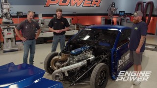
(Pat)>> When we arrived at work today we realized that a project that we've been extremely excited about is actually happening. Inside this beautiful Factory Five transporter is a one of a kind chassis that will become Engine Power's new test sled.
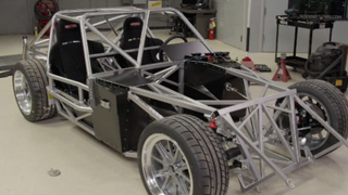
(Mike)>> It was engineered to be a rolling dyno of sorts. One that will accept bit and small block Chevys, Fords, Mopars, basically anything we can dream of. Now it was designed with simplicity in mind, and being a Factory Five we know it's gonna be safe, light weight, and have handling characteristics that any race car driver will envy.
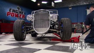
(Pat)>> Feast your eyes on the Type 65 Coupe-R meant for professional competition. This car was built for a web series featuring Joey Lagano. He drove the car at Charlotte Motor Speedway on their road course. It's basically a race version of the gen three coupe. It has a competition cage chassis that's twice as strong as the incredible gen three chassis. It's equipped with a five point two XS Illuminator Ford crate engine, TKO 600 road race transmission, and an independent rear suspension, and this is what we're so excited about, and how could we not be. This is the same Factory Five Type 65 Coupe-R chassis that's under that wicked looking race car.
(Mike)>> It was designed with structural rigidity, safety, drive compartment size, and space for extra head and foot room. Multiple suspension mounting points for street and race setups, and modular engine mounting for multiple engine and transmission platforms. It has a 95 inch wheel base, optional IRS or live axle rear end, front coil over independent suspension, plus multiple brake and wheel and tire combinations are available.
(Dave)>> I mean the coupe chassis is really our best race chassis, and it delivers a really confident feel. It's got so much strength and so much rigidity that it isolates the suspension, let's it do its job. And so behind the wheel it really comes alive, and I think it'll be the great test fixture for you guys taking an engine. Where you know it takes an engine from the dyno and it puts it into real life, and it really brings that engine alive and gives you guys a chance to compare engine based on really the different attributes of that engine instead of being distracted by apples and oranges on chassis.
(Mike)>> Not having a body makes it easier for us to install engines quickly, and with a chassis this wicked why cover it up.
(Dave)>> Some people want to go to a car show and see all the pretty cars. We want to see what's underneath it. That's what Factory Five does. So seeing our frame on display, that attracts a ton of eyes, and it gives us a chance to show off.
(Pat)>> From engineering to logistics we had a couple of guys from Factory Five to show us around this car, Jim Schenk and Chris Ronni. Now Jim this is your design. Tell me a little bit about the evolution of this car.
(Jim)>> So this is what we call a Gen Three Couple chassis. This is the competition version. So we basically re-did the coupe chassis with all this extra tube. Got rid of the vintage design and went to a much more modern, rigid. Basically said okay, we can hide all that vintage stuff but we can make the chassis perform at a high modern level.
(Pat)>> Wonderful, now it comes in a state that we normally don't do. It's actually half assembled. Tell me a little bit about from the back to the front.
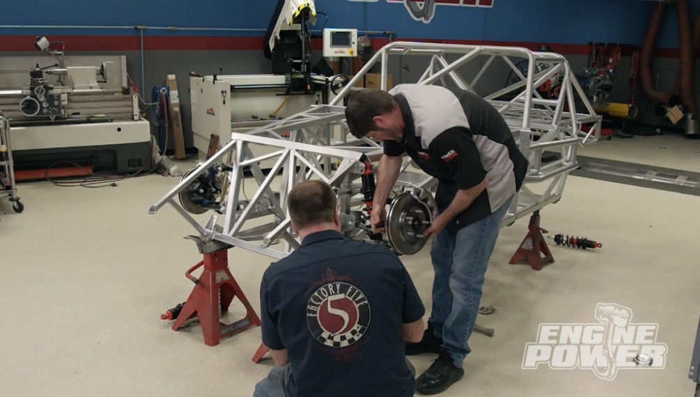
(Jim)>> So we just did some basic stuff to start out you know. We put one side suspension on. We put the differential in, ran some brake lines. Left the other side off that way you could see how it all goes together, but it's basically just a repeat of what's already on there. So it'll go together pretty quick to this stage.
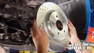
(Mike)>> The tubular lower control arm built in house at Factory Five is installed first, followed by a Koni coil over specifically setup for this chassis. The spindle and brake assembly is next. It's positioned on the lower ball joint. These are Mustang brakes. So if we ever want to upgrade the swap will be easy. Now the manual quick ratio steering rack can drop in. It mounts to the lower set of holes in the chassis. With everything in place a nut and bolt tightening party gets going. Giving us some steering support is a remote mounted electric steering assist box. Attached to it is a Factory Five wheel and splined adapter. The steering shaft is a collapsible design with splined joints. It makes the connection from the electric assist to the rack. The pedal box is pure race car hardware. From the pedals to the slave cylinders this screams track time. For a little extra support a Factory Five bracket is in place. Out back Pat finally gets his hands to work. This is a 15 gallon tank from a Fox body Mustang. A lower control arm goes in out back along with a c/v axle for the Ford Super Eight-Eight IRS rear.
(Jim)>> For now it's still basically a pretty standard chassis. If you wanted to put a body on it and finish it like the other coupes you could do it.
(Narrator)>> Pat goes on a joy ride while Mike works on body panels. I guess we know who won that bet.
(Pat)>> The Factory Five test sled is coming along nicely, and ready to receive body panels. This is meticulous, repetitive work, which is why Dave and I decided to take a break.
(Dave)>> Alright so we're going out this way right?
(Pat)>> Yeah.
(Dave)>> Alright well let me just straighten out the curve then. [ engine revving ]
(Pat)>> That's pretty. [ engine revving ]
(Pat)>> This thing is awesome. [ engine revving ]
(Dave)>> That was fun huh?
(Pat)>> Man that was really fun. [ air punch hissing ] [ drill spinning ]
(Mike)>> The guys even brought us a couple of race seats. These have great retainment and will accept the five point harnesses going in later. Wheels and tires are a must. Halibrand style 18 inch Factory Five wheels are wrapped in Mickey Thompson Street Comp tires. Now it's a complete roller. Alright Jim, ride height on this car. For the first little bit we're gonna do is easy street driving and stuff. What's the difference between the street and the race setup?
(Jim)>> So typically if we set it up for the race track we'll use the upper set of holes, which is a little over an inch lower. Set the ride height to three inches, three and an eighth. Here for street, you know speed bumps, and pot holes, that kind of stuff, we usually go about four and a half. That'll keep you off most things. Particularly with no body on this thing it'll be even more so cause there's really nothing in front of the front wheels to hit.
(Mike)>> The ride height is set first. The coil over adjustments will get us where we want to be.
Now the castor/camber gauge is put in place and adjustments are made on the upper control arm. We went for a mid-range setup that is not overly aggressive.
Toe was also set. we put it at a sixteenth of an inch toe in.
(Pat)>> Perfect.
(Mike)>> Guys we made it a long way today. All we have left to do is mount some gauge, run some battery cables, some fuel lines, and then the rest of it will happen when we drop the engine in.
(Pat)>> You know we've been after a project like this for a long time and now it's finally done, and it's more than what we expected. We know it as gonna be cool but we didn't know it was gonna be cool right? Now that it's here put together we can't thank you enough for this, and any hair brained idea that we hang in there I'm sure we're gonna need your technical expertise. So we'll still be talking to you, but thank you very much for everything you've done.
(Jim)>> Absolutely, it was fun to work with you guys again and we're only a phone call away.
(Pat)>> Thank you very much.
(Jim)>> I look forward to it.
(Pat)>> Let's head out. [ circuit breakers clicking off ]
(Narrator)>> Up next a brand new bullet gives BMR racing the ponies they need to succeed.
(Pat)>> Today we'll be moving forward with the build of our true race bullet that's designed to run strong and long in the endurance racing arena. This engine will run for 18 hours split over two days of action packed road course competition. It's being built for the BMR race team. A group of mid-Ohio sports car course instructors that have the passion and experience to compete in the American Endurance Race Series. The team pilots a moderately funded Fox body Mustang that runs against higher dollar makes such as Porsche, BMW, Ferrari, and Audi. With a stock power plant that has reached its limit BMR wants more power to compete in a higher class. Simply put they are pro drivers on weekend warrior's budget.
(Nan)>> Pros race in this series and sportsmen. So you have people racing with lots of money and the coolest equipment in the world, and people racing with smarts and driving skills. And of course the budgets match those. You have people with lots of money and we have people with lots of skill, and brains, and engineering skill, and we're really interested in that.
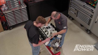
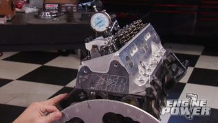
(Pat)>> Summit Racing, a sponsor of the endurance series, is helping BMR and their American made Mustang reach faster lap times with a vastly improved higher horsepower engine. They've given us the honor of building that power plant. It's 363 cubic inch small block Ford based on the Dart Iron Eagle engine block. So far we've made good progress on the project that included honing the cylinders, checking the deck height, deburring the block, and chamfering the cylinders. Then we gave engine protection from the elements with Dupli-Color's Ford blue engine enamel. BMR's color of choice. Main bearing clearances were setup, and after balancing the crank was torqued into place to start final assembly. Next to go in are the rod and piston assemblies, and for the connecting rod we chose an H-beam from Eagle Specialty Products. Now these are forged out of 43-40 steel and they have a five-400 center to center length. On the big end it's set up for a two-100 rod journal, and on the pin end it's set up for a nine-27 wrist pine. And because this will see engine speeds as high as 8,000 r-p-m an ARP 2,000 rod bolt will secure the cap. A full custom piston was made for this build because of the abuse it will see. We chose a set of DSS FX Series X-groove 26-18 alloy forgings. The patented XGroove extends the life of the cylinders, pistons, and ring seal. On the down stroke debris and excess oil are swept into the XGroove and exit the piston's oil drain back holes. Now this keeps the clearance between the piston and the cylinder wall cleaner and reduces oil load on the oil ring. On the up stroke when fuel washes down normal wear and break in debris are swept into the X-groove but exit into the oil pan, and this maintains an oil film on the most critical part of the skirts and cylinder walls. These pistons were sent to us with the PRK kit. It includes a one point two, one point two, three millimeter ring set to take the guess work out of getting the correct parts. For optimized ring seal in the upper r-p-m ranges horizontal gas ports were added. The pistons are available for small block Chevys, LS engines, and Fords. Before we final assemble the rod and piston assemblies we're gonna check rod bearing clearance, and just like the mains we need one thousandths per inch of shaft for vertical oil clearance. Now the diameter of the crank is two-100. So we need a minimum of 21 ten thousandths. In some cases a set of standard bearings won't give enough oil clearance and a set of one thousandths over, or X-bearings, will give too much. So what do you do in a case like that? Well I'm gonna show you. For an accurate clearance reading we carefully measure the journal with a calibrated micrometer and set our dial bore gauge to that precise measurement. Now we are ready to measure the rod bearing clearance. To give you an example I have three rods that are torqued up and the bolts stretched, and our dial bore is set to our crankshaft's diameter. Now what we're gonna do is measure this first one, which is the standard. It measure 17 ten thousandths, which is insufficient for what we're doing. With a standard set of X-bearings in which is a thousandths more clearance it will be a thousandths more than that, and if it's all done right we are at 27 ten thousandths. Will it work? Sure, but is it a little much for what we're doing? Of course! So what you can do in that situation is take a combination of a standard bearing and an X-bearing, which is a thousandths, which nets us only a half a thousandths of clearance increase. So on our combination we have a clearance of 23 ten thousandths. That's perfect for what we're trying to do with this endurance engine.
(Narrator)>> Up next, the right way to install rods and pistons.
(Pat)>> It has taken a while to get to this point but we're finally here. Everything has been measured and verified. So from now on it's gonna go pretty quick. We're gonna stick our rod and piston assemblies together, and we're gonna get them in our Dart block. The first order of business is installing the Eagle rod onto the DSS piston. We're using Permatex ultra slick engine assembly lube to prevent any scuffing of the wrist pin bores on initial startup.
The floating wrist pin is easily pushed in and is retained with double spiral locks. Take your time putting them in to make sure they are indexed into the groove. Next up the oil support rail gets installed, followed by the three millimeter oil ring pack.
Then the Napier style second ring is put in place.
And finally the steel top ring. High performance piston rings are typically thinner and require a little more attention to make sure they are installed correctly. Take your time. With everything lubed up an ARP tapered ring compressor is used to stuff the assemblies into the block.
Our dead blow piston knocker taps the piston easily into the bore. Then it is pushed down gently until it seats on the crankshaft. With ARP Ultra Torque on the rod bolts the caps are gently run onto the rods. With a slick hone job and plenty of lube in the cylinders everything goes together nicely.
[ drill spinning ]
(Pat)>> Anything worth doing is worth doing right. So we'll use our ARP rod bolt stretch gauge to properly torque the ARP 2,000 rod bolts. The proper stretch is between 64 and 68 ten thousandths, and that required 90 pound feet of torque from our Matco digital torque wrench. We're looking good with 64 ten thousandths of stretch. For more information on anything you've seen on today's show visit Powernation TV dot com. When we build engines here on Engine Power we use ARP studs and bolts. Now all of their fasteners are designed to withstand the intense heat, pressure, and stress of high performance automotive applications. Here's a look on how studs and bolts differ and why you'd use them in some situations. A bolt or stud works the same way but clamps differently. A bolt has to overcome two forces to apply its clamping load. The bolt not only stretches to load the threads, there is additional friction at the bolt head, which introduces twist into the fastener. Since a stud spreads its clamping loads between two sets of threads instead of one it's often used in high torque applications, like holding on cylinder heads or main caps in high stress situations, and for any information on fasteners visit ARP dash bolts dot com.
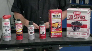
(Mike)>> If you've got a GDI engine CRC's GDI Service five in one performance rejuvenation pack is just what you need. It uses polyether amine to remove hard baked on carbon deposits from spark plugs, throttle bodies, intake valves, turbos, injectors, and combustion chambers. The plastic safe mass air flow sensor cleaner provides increased miles per gallon and fuel economy. The one tank power renew fluid treats up to 25 gallons of gasoline and cleans the complete fuel system. To find out more visit CRC Industries dot com.
(Pat)>> Here in Engine Power machining cylinder blocks, heads, and intake manifolds are just a few of the tasks that we can do on our mill and our lathe. Other things include making custom parts or tools to make our jobs easier, but not only for us, for all the other shops in the building.
(Mike)>> We also use them to complete other processes that involve tools not even associated with them. Like spinning a crankshaft at low r-p-m to properly polish it with the polisher. Now let's take a look at some of the other things we have done so you have an understanding of how these machines work and the unlimited jobs that can be done with the proper tooling. Let's start with the block being secured to the mill for a process that is very normal at a machine shop. When a rotating assembly with a larger stroke is being installed more than likely the block will need to be machined for rod bolt clearance. This involves removing material at the bottom of the cylinders and sometimes at the inner edge of the oil pan mounting rail.
(Pat)>> The tooling used to do this operation is a three quarter inch four flute end mill. It's used to plunge cut in small increments until the need clearance is reached. It's done in small increments to avoid tool deflection and tool wear. This same job can be done with a carbide burr but this way makes for a cleaner and more professional outcome.
(Mike)>> Another operation this machine can be used for is angle milling a valley cover for an LS engine. This was done because it sat too high and needed to be machined at the same angle as the deck's surface. The tooling that did this operation was a three inch index end mill, or sometimes known as a face mill. The mill head is set at the correct angle to cut the measured amount where it needs to be. The power feed was set, and the small increments were taken off until the cover was the proper size.
(Pat)>> The same index mill was also used to handle another in house project. This time a Cummins flywheel was mounted to a rotary table to remove two pounds of mass taken off the flywheel's face. A center was made in the lathe to dial in the flywheel's location. So the correct radius could be machined. If not centered it would turn in an ellipse, causing a problem.
(Mike)>> Like the mill, this lathe has been a huge asset and time saver. We've been able to make custom parts on the fly to keep project moving forward. A perfect example are the shock mounts for the Triple Threat Camaro. A little bar stock and a few minutes time we had shock bushings made up that were purpose built for our application. Tooling is just as important and that is something we will continue with next time.
(Pat)>> A well-equipped machine shop allows us to show you more tech and makes our projects more interesting and informative, and as time goes on more machines will be added so we can take a step forward every chance we get.
Show Full Transcript
(Pat)>> When we arrived at work today we realized that a project that we've been extremely excited about is actually happening. Inside this beautiful Factory Five transporter is a one of a kind chassis that will become Engine Power's new test sled.
(Mike)>> It was engineered to be a rolling dyno of sorts. One that will accept bit and small block Chevys, Fords, Mopars, basically anything we can dream of. Now it was designed with simplicity in mind, and being a Factory Five we know it's gonna be safe, light weight, and have handling characteristics that any race car driver will envy.
(Pat)>> Feast your eyes on the Type 65 Coupe-R meant for professional competition. This car was built for a web series featuring Joey Lagano. He drove the car at Charlotte Motor Speedway on their road course. It's basically a race version of the gen three coupe. It has a competition cage chassis that's twice as strong as the incredible gen three chassis. It's equipped with a five point two XS Illuminator Ford crate engine, TKO 600 road race transmission, and an independent rear suspension, and this is what we're so excited about, and how could we not be. This is the same Factory Five Type 65 Coupe-R chassis that's under that wicked looking race car.
(Mike)>> It was designed with structural rigidity, safety, drive compartment size, and space for extra head and foot room. Multiple suspension mounting points for street and race setups, and modular engine mounting for multiple engine and transmission platforms. It has a 95 inch wheel base, optional IRS or live axle rear end, front coil over independent suspension, plus multiple brake and wheel and tire combinations are available.
(Dave)>> I mean the coupe chassis is really our best race chassis, and it delivers a really confident feel. It's got so much strength and so much rigidity that it isolates the suspension, let's it do its job. And so behind the wheel it really comes alive, and I think it'll be the great test fixture for you guys taking an engine. Where you know it takes an engine from the dyno and it puts it into real life, and it really brings that engine alive and gives you guys a chance to compare engine based on really the different attributes of that engine instead of being distracted by apples and oranges on chassis.
(Mike)>> Not having a body makes it easier for us to install engines quickly, and with a chassis this wicked why cover it up.
(Dave)>> Some people want to go to a car show and see all the pretty cars. We want to see what's underneath it. That's what Factory Five does. So seeing our frame on display, that attracts a ton of eyes, and it gives us a chance to show off.
(Pat)>> From engineering to logistics we had a couple of guys from Factory Five to show us around this car, Jim Schenk and Chris Ronni. Now Jim this is your design. Tell me a little bit about the evolution of this car.
(Jim)>> So this is what we call a Gen Three Couple chassis. This is the competition version. So we basically re-did the coupe chassis with all this extra tube. Got rid of the vintage design and went to a much more modern, rigid. Basically said okay, we can hide all that vintage stuff but we can make the chassis perform at a high modern level.
(Pat)>> Wonderful, now it comes in a state that we normally don't do. It's actually half assembled. Tell me a little bit about from the back to the front.
(Jim)>> So we just did some basic stuff to start out you know. We put one side suspension on. We put the differential in, ran some brake lines. Left the other side off that way you could see how it all goes together, but it's basically just a repeat of what's already on there. So it'll go together pretty quick to this stage.
(Mike)>> The tubular lower control arm built in house at Factory Five is installed first, followed by a Koni coil over specifically setup for this chassis. The spindle and brake assembly is next. It's positioned on the lower ball joint. These are Mustang brakes. So if we ever want to upgrade the swap will be easy. Now the manual quick ratio steering rack can drop in. It mounts to the lower set of holes in the chassis. With everything in place a nut and bolt tightening party gets going. Giving us some steering support is a remote mounted electric steering assist box. Attached to it is a Factory Five wheel and splined adapter. The steering shaft is a collapsible design with splined joints. It makes the connection from the electric assist to the rack. The pedal box is pure race car hardware. From the pedals to the slave cylinders this screams track time. For a little extra support a Factory Five bracket is in place. Out back Pat finally gets his hands to work. This is a 15 gallon tank from a Fox body Mustang. A lower control arm goes in out back along with a c/v axle for the Ford Super Eight-Eight IRS rear.
(Jim)>> For now it's still basically a pretty standard chassis. If you wanted to put a body on it and finish it like the other coupes you could do it.
(Narrator)>> Pat goes on a joy ride while Mike works on body panels. I guess we know who won that bet.
(Pat)>> The Factory Five test sled is coming along nicely, and ready to receive body panels. This is meticulous, repetitive work, which is why Dave and I decided to take a break.
(Dave)>> Alright so we're going out this way right?
(Pat)>> Yeah.
(Dave)>> Alright well let me just straighten out the curve then. [ engine revving ]
(Pat)>> That's pretty. [ engine revving ]
(Pat)>> This thing is awesome. [ engine revving ]
(Dave)>> That was fun huh?
(Pat)>> Man that was really fun. [ air punch hissing ] [ drill spinning ]
(Mike)>> The guys even brought us a couple of race seats. These have great retainment and will accept the five point harnesses going in later. Wheels and tires are a must. Halibrand style 18 inch Factory Five wheels are wrapped in Mickey Thompson Street Comp tires. Now it's a complete roller. Alright Jim, ride height on this car. For the first little bit we're gonna do is easy street driving and stuff. What's the difference between the street and the race setup?
(Jim)>> So typically if we set it up for the race track we'll use the upper set of holes, which is a little over an inch lower. Set the ride height to three inches, three and an eighth. Here for street, you know speed bumps, and pot holes, that kind of stuff, we usually go about four and a half. That'll keep you off most things. Particularly with no body on this thing it'll be even more so cause there's really nothing in front of the front wheels to hit.
(Mike)>> The ride height is set first. The coil over adjustments will get us where we want to be.
Now the castor/camber gauge is put in place and adjustments are made on the upper control arm. We went for a mid-range setup that is not overly aggressive.
Toe was also set. we put it at a sixteenth of an inch toe in.
(Pat)>> Perfect.
(Mike)>> Guys we made it a long way today. All we have left to do is mount some gauge, run some battery cables, some fuel lines, and then the rest of it will happen when we drop the engine in.
(Pat)>> You know we've been after a project like this for a long time and now it's finally done, and it's more than what we expected. We know it as gonna be cool but we didn't know it was gonna be cool right? Now that it's here put together we can't thank you enough for this, and any hair brained idea that we hang in there I'm sure we're gonna need your technical expertise. So we'll still be talking to you, but thank you very much for everything you've done.
(Jim)>> Absolutely, it was fun to work with you guys again and we're only a phone call away.
(Pat)>> Thank you very much.
(Jim)>> I look forward to it.
(Pat)>> Let's head out. [ circuit breakers clicking off ]
(Narrator)>> Up next a brand new bullet gives BMR racing the ponies they need to succeed.
(Pat)>> Today we'll be moving forward with the build of our true race bullet that's designed to run strong and long in the endurance racing arena. This engine will run for 18 hours split over two days of action packed road course competition. It's being built for the BMR race team. A group of mid-Ohio sports car course instructors that have the passion and experience to compete in the American Endurance Race Series. The team pilots a moderately funded Fox body Mustang that runs against higher dollar makes such as Porsche, BMW, Ferrari, and Audi. With a stock power plant that has reached its limit BMR wants more power to compete in a higher class. Simply put they are pro drivers on weekend warrior's budget.
(Nan)>> Pros race in this series and sportsmen. So you have people racing with lots of money and the coolest equipment in the world, and people racing with smarts and driving skills. And of course the budgets match those. You have people with lots of money and we have people with lots of skill, and brains, and engineering skill, and we're really interested in that.
(Pat)>> Summit Racing, a sponsor of the endurance series, is helping BMR and their American made Mustang reach faster lap times with a vastly improved higher horsepower engine. They've given us the honor of building that power plant. It's 363 cubic inch small block Ford based on the Dart Iron Eagle engine block. So far we've made good progress on the project that included honing the cylinders, checking the deck height, deburring the block, and chamfering the cylinders. Then we gave engine protection from the elements with Dupli-Color's Ford blue engine enamel. BMR's color of choice. Main bearing clearances were setup, and after balancing the crank was torqued into place to start final assembly. Next to go in are the rod and piston assemblies, and for the connecting rod we chose an H-beam from Eagle Specialty Products. Now these are forged out of 43-40 steel and they have a five-400 center to center length. On the big end it's set up for a two-100 rod journal, and on the pin end it's set up for a nine-27 wrist pine. And because this will see engine speeds as high as 8,000 r-p-m an ARP 2,000 rod bolt will secure the cap. A full custom piston was made for this build because of the abuse it will see. We chose a set of DSS FX Series X-groove 26-18 alloy forgings. The patented XGroove extends the life of the cylinders, pistons, and ring seal. On the down stroke debris and excess oil are swept into the XGroove and exit the piston's oil drain back holes. Now this keeps the clearance between the piston and the cylinder wall cleaner and reduces oil load on the oil ring. On the up stroke when fuel washes down normal wear and break in debris are swept into the X-groove but exit into the oil pan, and this maintains an oil film on the most critical part of the skirts and cylinder walls. These pistons were sent to us with the PRK kit. It includes a one point two, one point two, three millimeter ring set to take the guess work out of getting the correct parts. For optimized ring seal in the upper r-p-m ranges horizontal gas ports were added. The pistons are available for small block Chevys, LS engines, and Fords. Before we final assemble the rod and piston assemblies we're gonna check rod bearing clearance, and just like the mains we need one thousandths per inch of shaft for vertical oil clearance. Now the diameter of the crank is two-100. So we need a minimum of 21 ten thousandths. In some cases a set of standard bearings won't give enough oil clearance and a set of one thousandths over, or X-bearings, will give too much. So what do you do in a case like that? Well I'm gonna show you. For an accurate clearance reading we carefully measure the journal with a calibrated micrometer and set our dial bore gauge to that precise measurement. Now we are ready to measure the rod bearing clearance. To give you an example I have three rods that are torqued up and the bolts stretched, and our dial bore is set to our crankshaft's diameter. Now what we're gonna do is measure this first one, which is the standard. It measure 17 ten thousandths, which is insufficient for what we're doing. With a standard set of X-bearings in which is a thousandths more clearance it will be a thousandths more than that, and if it's all done right we are at 27 ten thousandths. Will it work? Sure, but is it a little much for what we're doing? Of course! So what you can do in that situation is take a combination of a standard bearing and an X-bearing, which is a thousandths, which nets us only a half a thousandths of clearance increase. So on our combination we have a clearance of 23 ten thousandths. That's perfect for what we're trying to do with this endurance engine.
(Narrator)>> Up next, the right way to install rods and pistons.
(Pat)>> It has taken a while to get to this point but we're finally here. Everything has been measured and verified. So from now on it's gonna go pretty quick. We're gonna stick our rod and piston assemblies together, and we're gonna get them in our Dart block. The first order of business is installing the Eagle rod onto the DSS piston. We're using Permatex ultra slick engine assembly lube to prevent any scuffing of the wrist pin bores on initial startup.
The floating wrist pin is easily pushed in and is retained with double spiral locks. Take your time putting them in to make sure they are indexed into the groove. Next up the oil support rail gets installed, followed by the three millimeter oil ring pack.
Then the Napier style second ring is put in place.
And finally the steel top ring. High performance piston rings are typically thinner and require a little more attention to make sure they are installed correctly. Take your time. With everything lubed up an ARP tapered ring compressor is used to stuff the assemblies into the block.
Our dead blow piston knocker taps the piston easily into the bore. Then it is pushed down gently until it seats on the crankshaft. With ARP Ultra Torque on the rod bolts the caps are gently run onto the rods. With a slick hone job and plenty of lube in the cylinders everything goes together nicely.
[ drill spinning ]
(Pat)>> Anything worth doing is worth doing right. So we'll use our ARP rod bolt stretch gauge to properly torque the ARP 2,000 rod bolts. The proper stretch is between 64 and 68 ten thousandths, and that required 90 pound feet of torque from our Matco digital torque wrench. We're looking good with 64 ten thousandths of stretch. For more information on anything you've seen on today's show visit Powernation TV dot com. When we build engines here on Engine Power we use ARP studs and bolts. Now all of their fasteners are designed to withstand the intense heat, pressure, and stress of high performance automotive applications. Here's a look on how studs and bolts differ and why you'd use them in some situations. A bolt or stud works the same way but clamps differently. A bolt has to overcome two forces to apply its clamping load. The bolt not only stretches to load the threads, there is additional friction at the bolt head, which introduces twist into the fastener. Since a stud spreads its clamping loads between two sets of threads instead of one it's often used in high torque applications, like holding on cylinder heads or main caps in high stress situations, and for any information on fasteners visit ARP dash bolts dot com.
(Mike)>> If you've got a GDI engine CRC's GDI Service five in one performance rejuvenation pack is just what you need. It uses polyether amine to remove hard baked on carbon deposits from spark plugs, throttle bodies, intake valves, turbos, injectors, and combustion chambers. The plastic safe mass air flow sensor cleaner provides increased miles per gallon and fuel economy. The one tank power renew fluid treats up to 25 gallons of gasoline and cleans the complete fuel system. To find out more visit CRC Industries dot com.
(Pat)>> Here in Engine Power machining cylinder blocks, heads, and intake manifolds are just a few of the tasks that we can do on our mill and our lathe. Other things include making custom parts or tools to make our jobs easier, but not only for us, for all the other shops in the building.
(Mike)>> We also use them to complete other processes that involve tools not even associated with them. Like spinning a crankshaft at low r-p-m to properly polish it with the polisher. Now let's take a look at some of the other things we have done so you have an understanding of how these machines work and the unlimited jobs that can be done with the proper tooling. Let's start with the block being secured to the mill for a process that is very normal at a machine shop. When a rotating assembly with a larger stroke is being installed more than likely the block will need to be machined for rod bolt clearance. This involves removing material at the bottom of the cylinders and sometimes at the inner edge of the oil pan mounting rail.
(Pat)>> The tooling used to do this operation is a three quarter inch four flute end mill. It's used to plunge cut in small increments until the need clearance is reached. It's done in small increments to avoid tool deflection and tool wear. This same job can be done with a carbide burr but this way makes for a cleaner and more professional outcome.
(Mike)>> Another operation this machine can be used for is angle milling a valley cover for an LS engine. This was done because it sat too high and needed to be machined at the same angle as the deck's surface. The tooling that did this operation was a three inch index end mill, or sometimes known as a face mill. The mill head is set at the correct angle to cut the measured amount where it needs to be. The power feed was set, and the small increments were taken off until the cover was the proper size.
(Pat)>> The same index mill was also used to handle another in house project. This time a Cummins flywheel was mounted to a rotary table to remove two pounds of mass taken off the flywheel's face. A center was made in the lathe to dial in the flywheel's location. So the correct radius could be machined. If not centered it would turn in an ellipse, causing a problem.
(Mike)>> Like the mill, this lathe has been a huge asset and time saver. We've been able to make custom parts on the fly to keep project moving forward. A perfect example are the shock mounts for the Triple Threat Camaro. A little bar stock and a few minutes time we had shock bushings made up that were purpose built for our application. Tooling is just as important and that is something we will continue with next time.
(Pat)>> A well-equipped machine shop allows us to show you more tech and makes our projects more interesting and informative, and as time goes on more machines will be added so we can take a step forward every chance we get.
